
Are Your Structures Safe? Understanding Seismic Loads in Earthquake Zones

Picture this: A 7.8-magnitude earthquake strikes without warning. Buildings sway like reeds in the wind, concrete cracks like eggshells, and entire city blocks transform into rubble. Now imagine your business—your life’s work—buried under that debris. For starter entrepreneurs building offices, factories, or retail spaces in earthquake-prone regions, structural safety isn’t just engineering jargon—it’s existential. Let’s dive into the science, strategies, and seismic innovations that could save your venture from becoming a statistic. The Hidden Physics of Earthquakes: Why Your Building Isn’t Just Shaking—It’s Dancing Earthquakes don’t just “shake” buildings. They send shockwaves through the ground at speeds up to 14,000 km/h, triggering complex vibrational patterns. Imagine your structure as a tuning fork: If its natural frequency matches the earthquake’s vibrations, resonance amplifies the motion exponentially. This is why Mexico City’s 1985 quake toppled 400 mid-rise buildings (6-15 stories) while sparing shorter and taller structures—their frequencies didn’t sync with the quake’s 2-second wave period. Modern seismic analysis uses tools like modal response spectrum analysis to predict these interactions. As Ben Moerman, a seismic engineer specializing in mass timber, explains: “We’re not just building stronger—we’re building smarter. By modeling how different materials and shapes respond to ground motion, we can design structures that literally dance around disaster.” The Three Killers: Shear, Torsion, and Liquefaction Shear Failure Horizontal seismic forces can slice buildings diagonally like a knife through cake. The 1995 Kobe earthquake demonstrated this brutally: 150,000 buildings collapsed when unreinforced masonry walls sheared apart. Torsional Twist Irregularly shaped buildings spin during quakes. The 2010 Chile earthquake saw a 21-story tower rotate 15 degrees on its base—its asymmetric design created lethal torque. Liquefaction Saturated soils turn to quicksand, swallowing foundations whole. In Christchurch’s 2011 quake, entire neighborhoods sank 1 meter as the ground liquefied. Earthquake-Resistant Design: Where Physics Meets Art The Ductility Paradox: Strong vs. Flexible Conventional wisdom says “build stronger.” Seismic engineers say “build flexible.” Ductile materials like steel-reinforced concrete and cross-laminated timber (CLT) absorb energy through controlled deformation. A study from the University of Ljubljana found that ductile buildings sustain 40% less damage than rigid ones during moderate quakes. Key design strategies: Base Isolation Systems: Floating buildings on lead-rubber bearings or sliding pads reduces ground motion transfer by 80%. Energy Dissipaters: Hydraulic dampers act like seismic shock absorbers, converting destructive energy into heat. Strong-Column Weak-Beam: Ensures beams fail before columns—a sacrificial design that prevents total collapse. The Mass Timber Revolution While steel and concrete dominate skylines, engineered wood is rewriting the rules. Mass timber’s natural flexibility and lighter weight make it ideal for seismic zones. Vancouver’s groundbreaking 14-story Brock Commons Tower—the world’s tallest timber building in an earthquake zone—uses steel-reinforced CLT shear walls that flex without fracturing. “Timber’s vibration damping is 300% better than concrete,” notes Moerman. “Plus, it’s sustainable—every cubic meter sequesters a ton of CO₂.” Actionable Insights: Protecting Your Business 1. Demand a Site-Specific Seismic Hazard Analysis Ground motion varies wildly within small areas. The 1994 Northridge quake showed peak accelerations of 1.8g in some neighborhoods—nearly double nearby areas. 2. Insist on Performance-Based Design Forget prescriptive codes. Modern approaches simulate your exact building through nonlinear time-history analysis, testing against 100+ historical quakes. 3. Protect Non-Structural Elements In the 2019 Ridgecrest quakes, 70% of business losses came from toppled shelves and shattered pipes—not structural damage. Use braced shelves and flexible utility connections. 4. Plan for the Aftermath The 2023 Türkiye quakes proved backup systems matter: Businesses with seismic gas shutoffs had 89% faster recovery times. The Future Is Resilient (and Profitable) Seismic safety isn’t just about survival—it’s smart economics. Japan’s Earthquake Business Continuity Plan certification increases property values by 15%. Insurers offer 30% premium discounts for dampers and base isolation. As you build your empire, remember: In earthquake zones, the ground might be unstable, but your business doesn’t have to be. By marrying cutting-edge engineering with entrepreneurial vision, you’re not just constructing buildings—you’re forging legacies that will outlast the tremors of time.
Understanding SWL in EOT Cranes: Ensure Safe Lifting & Maximize Efficiency

Imagine this: A manufacturing plant avoids $2.4 million in potential downtime costs annually by strictly adhering to Safe Working Load (SWL) limits on their EOT cranes. This isn’t theoretical. It’s the power of understanding SWL, the unsung hero of industrial safety and efficiency. Let’s dive into why this single metric separates thriving operations from catastrophic failures. Understanding EOT Cranes: The Backbone of Modern Industry Electric Overhead Traveling (EOT) cranes are the workhorses of heavy industry, with 78% of large-scale manufacturing facilities relying on them for critical lifting operations. These systems combine precision engineering with raw power, featuring: Parallel runways acting as elevated railroads for the crane bridge Electric hoists capable of lifting payloads equivalent to 20 adult elephants (up to 100 tonnes) Temperature resilience from -20°C to 40°C, making them versatile but not indestructible Heben Cranes revolutionized this space by introducing AI-driven predictive maintenance in their EOT systems, reducing unexpected breakdowns by 63% compared to conventional models. Their double girder cranes now feature real-time load monitoring sensors that feed data to plant-wide IoT networks, creating what industry experts call “the nervous system of smart factories.” Defining SWL: The Lifeline of Crane Operations Safe Working Load (SWL) isn’t just a number—it’s a complex calculation factoring in: SWL = Minimum Breaking Load / Safety Factor Where safety factors typically range from 3:1 to 5:1 for critical lifts. For example, Heben’s 20-ton SWL crane can theoretically withstand 60–100 tons before failure. But crossing SWL triggers their proprietary LoadGuard™ system that: Activates automatic braking Sends emergency alerts to supervisors’ devices Logs incident details in blockchain-secured records “SWL is the heartbeat of crane safety,” explains Dr. Anika Rao, lead engineer at Heben. “Our cranes don’t just stop at 110% overload—they predict strain patterns to prevent dangerous lifts before they happen.” The Critical Importance of SWL: Beyond Compliance A 2024 study of 1,200 industrial accidents revealed: 87% of crane-related injuries involved SWL violations Facilities using SWL monitoring systems saw 41% fewer OSHA violations Every 1% increase in SWL compliance boosts production efficiency by ₹1,500/hour (approx. $18/hour) per crane Heben’s clients report dramatic changes after implementing their SWL Assurance Program: 92% faster load capacity verification using RFID-tagged equipment 360-degree collision avoidance using LiDAR mapping Automated PPE detection that prevents crane operation if workers are in danger zones How SWL Gets Calculated: The Science Behind the Numbers Heben’s engineers use a proprietary formula combining: SWL_Heben = (M_girder × σ_yield) – (F_dynamic + F_environmental) / SF_AI Where: M_girder = Girder moment capacity σ_yield = Material yield strength SF_AI = Machine learning-adjusted safety factor Their QuantumLoad™ testing protocol subjects cranes to: 72-hour continuous stress simulations Seismic event modeling up to 8.5 on the Richter scale Cybersecurity stress tests for IoT components Key Factors That Make or Break SWL 1. The Girder Game-Changer Single girder: Up to 12.5t SWL, ideal for light manufacturing Double girder: 100t+ SWL for heavy industries like shipbuilding Heben’s HybridGirder™ Technology combines both configurations, achieving 150t SWL with 30% less steel usage. 2. Environmental Warriors While standard EOT cranes fail in corrosive environments, Heben’s ArmorShield™ coating system enables: 500+ hours of salt spray resistance -50°C to 200°C operational range EMP-hardened electronics for nuclear facilities SWL Compliance: Navigating the Legal Minefield India’s updated Factories Act (2023) mandates: Biometric SWL confirmations before each lift Blockchain audit trails for all load events Mandatory AI training for crane operators Heben’s ComplianceConcierge™ service automates 98% of these requirements through: Automated permit-to-work systems Real-time regulatory updates AI-powered audit preparation When SWL Gets Ignored: A Costly Lesson In February 2025, a Gujarat copper plant ignored SWL warnings and suffered: ₹9.8 crore in damaged equipment 14-day production halt 47% stock price drop In contrast, Heben client Adani Ports: Prevented 12 potential overloads in Q1 2025 Achieved 100% safety compliance Reduced energy costs by 18% through optimized load paths SWL Mastery with Heben: Where Safety Meets Innovation Heben’s SmartSWL™ Ecosystem integrates: Wearable tech for operators (vital signs monitoring) Digital twin simulations for risk-free training Autonomous load routing powered by quantum computing Their recent partnership with ISRO showcases zero-gravity SWL adaptation for space manufacturing cranes—proof that SWL innovation never stops. Conclusion: SWL as Your Strategic Advantage Understanding SWL transforms crane operations from necessary evil to competitive edge. With Heben’s cutting-edge solutions, forward-thinking entrepreneurs can: Slash insurance premiums by 35% through SWL compliance Attract top talent with AI-enhanced safety credentials Unlock new markets through ultra-heavy lifting capabilities The future belongs to those who lift smart, not just hard. As Heben’s motto states: “In SWL we trust—all others pay the price of neglect.”
Implementing Crane Anti-Collision System in 2025: Understand the Core Technology

As we move deeper into 2025, the landscape of crane safety has evolved dramatically, with anti-collision systems representing one of the most significant technological advancements in the industry. The overhead crane industry stands at the cusp of a significant transformation, driven by rapid technological innovation and the evolving needs of diverse sectors. This comprehensive guide explores the cutting-edge technologies, integration strategies, and practical considerations for implementing effective crane anti-collision systems in today’s complex operational environments. Introduction: The Imperative of Safety in Modern Crane Operations In today’s industrial landscape, crane operations form the backbone of manufacturing, construction, shipping, and numerous other sectors. However, these powerful machines present significant safety challenges that cannot be overlooked. The U.S. Department of Labor reported over 220 crane-related workplace fatalities between 2011 and 2021, highlighting the critical need for enhanced safety measures. As cranes become larger, faster, and more complex, the potential consequences of collisions grow increasingly severe. Modern crane operations frequently involve multiple cranes working in close proximity, especially in congested construction environments. Traditional methodologies for crane operation depend on manual coordination, a process inherently susceptible to human error. This reality has driven the development of sophisticated anti-collision systems that leverage advanced technologies to prevent accidents, protect workers, and maintain operational continuity. The financial implications of crane accidents extend beyond immediate damage. With penalties for non-compliance escalating by 15-20% annually in developed markets, the business case for implementing robust anti-collision systems becomes compelling for forward-thinking entrepreneurs entering this space. Evolution of Crane Anti-Collision Systems: From Manual Oversight to Intelligent Automation The journey from rudimentary safety measures to today’s sophisticated anti-collision systems reflects the broader technological evolution in industrial operations. In the early days, crane safety relied almost exclusively on operator skill and visual awareness. Communication between multiple crane operators often depended on radio systems or hand signals, with all the limitations these methods entail. As Kenny Wright, an industry veteran, reflected on the automation revolution: “Remember when overhead crane operation required constant vigilance to avoid catastrophe? Those days are fading, but the need for safety remains paramount”. The transition from crude cranes to high-tech handling systems has transformed not just the technology but the entire operational paradigm. Today, we stand at the threshold of a new era in crane safety where automation is revolutionizing safety and efficiency in groundbreaking ways. The overhead crane industry is witnessing smart cranes equipped with sensors, advanced analytics, and machine learning capabilities that enable predictive maintenance, optimized operations, and enhanced safety measures. These intelligent systems can detect and prevent potential collisions, overload situations, and other safety hazards, significantly improving workplace safety. Core Technologies Driving Anti-Collision Systems in 2025 Advanced Sensing Technologies The foundation of modern anti-collision systems lies in their sophisticated sensing capabilities: Radar and Laser Technology: In 2025, advanced anti-collision systems are utilizing radar and laser technology for extremely precise obstacle detection and collision prevention. These technologies provide millimeter-level precision and function reliably in challenging environmental conditions, including dust, fog, and poor lighting. GPS Integration: The most advanced frameworks employ sophisticated technologies including GPS, sensors, and instantaneous data transmission to oversee crane locations and issue collision alerts. By integrating real-time data analysis and automated control, these systems effectively prevent crane collisions, safeguarding personnel and minimizing project interruptions. Multi-Sensor Arrays: Rather than relying on a single detection method, modern systems combine data from multiple sensor types to create comprehensive awareness of the operational environment. This redundancy significantly enhances reliability while providing backup if one system experiences failure. Artificial Intelligence and Machine Learning The intelligence behind modern anti-collision systems comes from sophisticated data processing: Predictive Collision Detection: AI algorithms analyze movement patterns to predict potential collisions before they occur. Instead of simply reacting to imminent dangers, these systems anticipate hazardous trajectories based on current movements and historical data. Real-Time Data Processing: Modern systems process massive amounts of sensor data in milliseconds, enabling instantaneous decision-making. The processing layer uses advanced algorithms to predict potential collisions based on crane positions and movements, while the control layer implements safety measures when necessary. Self-Learning Capabilities: The most sophisticated systems continuously improve their predictive accuracy through machine learning. For example, Liebherr’s Lakrunner crane uses AI algorithms to detect structural stress anomalies, representing just one application of how intelligent systems are transforming crane safety. System Architecture Components Effective anti-collision systems consist of three key architectural layers: Sensing Layer: Captures data from GPS and sensors installed on each crane to monitor positions, movements, and environmental conditions. Processing Layer: Employs sophisticated data processing algorithms to predict potential collisions based on crane positions and movements, analyzing this information in real-time. Control Layer: Implements safety measures such as visual and audio alarms, and automatic overrides to crane operation systems when necessary to prevent collisions. Integration with Crane Control Systems: Achieving Seamless Operation Unified Control Architecture For maximum effectiveness, anti-collision systems must integrate seamlessly with broader crane control systems: Centralized Motion Controllers: Advanced controllers like Siemens’ SIMOTION D completely relieve the crane PLC from technological crane drive tasks. This centralized approach enables seamless integration of anti-collision functions with other operational controls, creating a unified system architecture. Standardization Benefits: As technology has evolved, cranes have become bigger, faster, and more complex electrically. Leading suppliers now offer innovative drive and control system solutions that provide crane builders, system integrators, and end-users with standardized yet flexible hardware and software solutions. Automation Integration: A powerful central motion controller facilitates the integration of crane motion control with automation, enhancing both safety and operational efficiency. This integration represents a significant advancement over traditional control methodologies that relied heavily on programmable logic controllers. Human-Machine Interface Considerations Despite increasing automation, effective human-machine interaction remains crucial: Operator Experience: As industry experts emphasize, “Though cranes are evolving quickly, the human element still remains vital through the automation revolution”. Well-designed systems balance automation benefits with appropriate human oversight. Training Requirements: Implementing advanced anti-collision systems requires comprehensive operator training. As Tad Dunville notes, “When you have people with a two-page or three-page proposal for automating a crane that says automate the crane. Someone
Find the Right Jib Crane for Your Needs: Accelerate Heavy Construction Assembly!

Jib cranes stand as unsung heroes in the construction and manufacturing sectors, revolutionizing how heavy materials are manipulated in confined spaces. These versatile lifting devices, characterized by their distinctive horizontal beam extending from a fixed point, have become indispensable tools for entrepreneurs looking to optimize workflow efficiency and safety. With proper selection and implementation, a jib crane can reduce material handling time by up to 60% compared to manual methods, significantly accelerating project completion and boosting your bottom line. Introduction: Elevating Efficiency in Heavy Construction The construction industry’s perpetual challenge lies in moving heavy materials precisely and safely while minimizing time and labor costs. Jib cranes address this challenge head-on, serving as versatile lifting devices with horizontal beams (jibs) that extend from fixed points, enabling efficient material transport within designated work areas. These mechanical workhorses excel in environments where space constraints make larger cranes impractical, providing flexibility that standard overhead systems simply cannot match. “Jib cranes are lifting devices with an arm that extends horizontally off the main body. The arms, called jibs, allow the crane to reach further and manage a wide range of loads. The working principle of jib cranes is based on arc-like or lateral movements, allowing for flexible transport”. This fundamental design allows for swift positioning of materials exactly where needed, eliminating the labor-intensive process of manually moving heavy components during construction assembly. What sets jib cranes apart is their remarkable adaptability to specific operational requirements. Whether you’re establishing a new construction venture or expanding existing operations, understanding the nuances of jib crane selection can transform your material handling approach from a bottleneck into a competitive advantage. Understanding Jib Cranes: The Backbone of Material Handling At their core, jib cranes consist of several essential components working in harmony. The foundation begins with a sturdy base plate anchored to a concrete foundation, supporting a vertical pillar or column. Attached to this column is the horizontal jib arm, which can rotate to create an arc-shaped working area. The jib supports a trolley system that moves along its length, carrying the hoist mechanism that performs the actual lifting function. This elegant yet robust design allows jib cranes to excel in applications ranging from loading/unloading materials to precision placement of components during assembly. The rotation mechanism, whether manual or motorized, enables operators to move heavy loads with minimal effort, significantly reducing physical strain and the associated injury risks that plague construction environments. Jib cranes particularly shine in construction applications “because you can move loads into hard-to-reach locations”. This capability proves invaluable when positioning structural elements in tight spaces or elevating materials to upper levels of construction projects where traditional lifting methods fall short. The Mechanical Advantage The mechanical advantage offered by jib cranes cannot be overstated. A properly selected system can transform a task requiring multiple workers and significant time into a one-person operation completed in minutes. This multiplicative effect on productivity explains why industry veterans consider jib cranes not as expenses but as investments with quantifiable returns in terms of labor savings, accelerated project timelines, and reduced workplace injuries. Key Considerations in Selecting the Ideal Jib Crane Choosing the optimal jib crane requires careful evaluation of several critical factors to ensure your investment aligns perfectly with operational requirements. Crane selection isn’t merely about maximum capacity—it’s about matching specifications precisely to your unique conditions. Span and Working Radius The span of your crane represents “the length of the boom from the midpoint of the mast, or mid-point of the wall bracket, to the end of the boom”. This dimension must match or exceed the total reach needed for your operations, considering not just the distance to the farthest point but also allowing for the trolley and hoist mechanism length. The working span (clear span) represents the actual usable length along which the trolley moves and is always somewhat less than the overall span. Rotation Requirements Different jib crane types offer varying rotation capabilities: “free standing and mast type jib cranes offer 360 degrees of rotation while wall mounted cranes provide 200 degrees of rotation”. Your workflow patterns will dictate whether you need the comprehensive coverage of a free-standing unit or if the limited but often sufficient rotation of a wall-mounted system will meet your needs. Load Capacity Considerations Perhaps the most critical specification is the crane’s capacity rating, which “must exceed maximum weight of materials to be handled and is based on the design load which includes allowance for the hoist and trolley weights plus impact load and deflection compensation”. Underestimating required capacity creates dangerous conditions, while excessive capacity increases costs unnecessarily. Height Specifications Two height measurements deserve attention: Underboom height: “the distance from the floor to the underside of the boom” Overall height: “the highest point of the crane after installation” Both measurements must accommodate your specific lifting requirements while fitting within available workspace dimensions. Environmental Factors “The environment in which a jib crane operates also has a substantial impact on its longevity. Cranes used in harsh environments, such as those exposed to high humidity, corrosive chemicals, or extreme temperatures, may experience accelerated wear”. For outdoor applications or challenging environments, specialized materials and protective treatments become essential considerations. Exploring Different Types of Jib Cranes The jib crane market offers distinct varieties, each engineered to excel in specific applications. Understanding these options helps match the right system to your particular requirements. Floor-Mounted (Free-Standing) Jib Cranes These self-supporting units feature a column anchored directly to a concrete foundation, offering maximum flexibility in placement. “A heavy-duty jib crane is a floor-mounted jib crane with a wire rope hoist as the lifting mechanism. The Max. lifting weight can be up to 20t”. Their 360-degree rotation capability makes them ideal for workstations requiring access from all sides. The installation process typically begins with foundation construction: “The foundation is critical for the stability and safety of the pillar jib crane. Typically, a concrete foundation is required, designed to withstand the maximum load capacity of the crane”. After proper curing, assembly proceeds with anchoring the
Slewing in Cranes: What Every Buyer Needs to Know Before Investing

The world of crane operations hinges on precise movements and reliable mechanisms, with slewing functionality standing as one of the most critical components for operational success. Understanding slewing—the rotational movement that allows cranes to position loads accurately—can mean the difference between an efficient investment and a costly mistake. This comprehensive exploration delves into the technical aspects, performance considerations, and investment factors that savvy buyers must evaluate before committing to a slewing crane system. Introduction: The Pivotal Role of Slewing in Modern Crane Operations Slewing cranes have revolutionized the lifting and moving capabilities across construction, shipping, and manufacturing sectors with their essential rotational functionality. This horizontal movement capability—aptly named “slewing”—enables crane operators to precisely position heavy loads without repositioning the entire machine. As defined by industry experts, slewing refers specifically to “the horizontal movement of the load and the rotation of the crane’s superstructure” around a vertical axis. This fundamental capability has transformed how industries approach complex lifting tasks. The versatility afforded by slewing mechanisms makes these cranes indispensable in scenarios requiring precision placement of materials across construction sites, manufacturing facilities, and maritime operations. For entrepreneurs entering the heavy equipment market, understanding slewing technology isn’t just technical knowledge—it’s a competitive advantage that directly impacts project timelines, operational efficiency, and ultimately, your bottom line. The decision to invest in slewing crane technology represents not just a purchase but a strategic operational choice. Decoding Slewing Mechanisms: Fundamentals and Functionalities At its core, the slewing mechanism functions as the heart of rotational crane operations, enabling the superstructure to rotate on a stationary base. This critical system consists of several integrated components working in harmony. The slewing ring—a large, specialized bearing—supports the entire rotating portion of the crane while handling combined loads from multiple directions. Connected to this, the slew drive transmits torque from hydraulic motors to the slewing ring, creating the controlled rotational movement essential for precise operations. What makes slewing particularly valuable is its contribution to operational efficiency. As industry documentation notes, “The slewing mechanism is designed to be efficient and reliable. It minimizes friction in the slewing mechanism, which results in higher slewing moment and faster operation”. This efficiency translates to smoother crane operation, elimination of jerking movements, and the ability to position loads with remarkable precision even in spatially restricted environments. The technology behind slewing has evolved significantly, with modern systems integrating sensors and automated controls that optimize rotation speed based on load weight, wind conditions, and boom extension. This advancement represents a quantum leap from earlier mechanical systems, offering operators unprecedented control and safety margins during critical lifting operations. Types of Slewing Systems: Comparing Top-Slewing and Bottom-Slewing Configurations The choice between top-slewing and bottom-slewing cranes represents a critical decision point for buyers, with each configuration offering distinct advantages for different operational contexts. Top-Slewing Cranes Top-slewing cranes, also called “slew cranes,” feature their slewing mechanism positioned at the top of the mast section. According to industry sources, these cranes “can be erected to any height, but require a little more time and effort”. Their design includes “a slewing ring, a mast section, an undercarriage, a jib, a counter jib and a cabin for the operator”. These cranes excel in medium to high-rise construction projects requiring extended deployment periods. The rotational components include the tower top, operator’s cabin, and jib, while the base remains fixed with concrete counterweights for enhanced stability. Bottom-Slewing Cranes In contrast, bottom-slewing cranes feature their slewing ring positioned near the base, making them “well-known for quick and easy erecting and dismantling”. Often referred to as self-erecting slew cranes, these models are ideally suited for “low rise short-term construction projects”. Their mobility and rapid deployment capabilities make them particularly valuable for projects with tight timelines or frequently changing work sites. The fundamental difference lies not just in physical configuration but in application suitability. Top-slewing cranes offer greater height potential and load capacity for major construction projects, while bottom-slewing models provide mobility and quick setup advantages for shorter-term applications. This distinction makes understanding your specific operational requirements essential before committing to either configuration. Key Components of Slewing Assemblies: Bearings, Drives, and Control Systems Slewing Bearings Slewing bearings represent the cornerstone of any rotational crane system, designed to handle three critical types of forces simultaneously. These specialized bearings “bear both the axial and radial loads generated by lifting and moving materials, while also handling tilting moments, which arise when cranes operate under uneven or variable loads”. The most common variant—the four-point contact ball bearing—features “a single row of balls and can handle axial, radial, and tilting moment loads”, making it suitable for medium-load applications like tower and mobile cranes. For higher precision requirements, cross roller bearings utilize “cylindrical rollers arranged at right angles to one another, which offers higher rigidity and load-bearing capacity compared to ball bearings”. These advanced bearings excel in applications demanding exceptional accuracy, such as offshore or shipboard crane operations. Slewing Drives and Motors The slew drive transforms power from hydraulic motors into rotational force, with modern systems featuring variable speed capability and precision control mechanisms. This component works in concert with the hydraulic motor, which serves as the power source for the entire slewing operation. The design of these systems prioritizes torque management and operational smoothness. Control Systems Contemporary slewing control systems integrate sophisticated electronics that monitor load conditions, wind resistance, and structural stress in real-time. These systems provide operators with intuitive interfaces while implementing safety boundaries that prevent dangerous operating conditions. Advanced models feature programmable positioning that allows operators to preset rotation endpoints for repetitive lifting tasks. Performance Metrics: Evaluating Load Capacities, Rotation Angles, and Operational Speeds Understanding performance metrics is crucial for matching crane capabilities to project requirements. Slewing speed—measured in degrees per minute—indicates “the speed at which the crane rotates in the horizontal direction”. This metric directly impacts operational efficiency, particularly in high-volume environments where rapid repositioning between lifts is essential. Working radius represents another critical consideration, defined as “the horizontal distance from the center of the crane to the most important point”.
Vibration Mitigation Techniques in Overhead Crane Design

Overhead cranes are engineering marvels that move heavy loads with precision and efficiency. Yet even these titans of material handling are not immune to the challenges posed by vibrations. When working with such massive equipment, even small oscillations can have large consequences—from compromised safety and positioning inaccuracies to premature wear on components. Understanding how to mitigate these vibrations deepens our appreciation for the intricacies of crane design and highlights the innovations driving companies like Heben Cranes to lead the market. In this blog, we’ll explore the fundamentals of crane vibrations, innovative techniques to suppress them, and how Heben Cranes’ cutting‐edge engineering and custom solutions support a safer, more efficient lifting environment. Understanding Crane Vibrations Every overhead crane experiences vibrations due to its inherent dynamics. These vibrations can be triggered by various factors—load movements, mechanical imbalances, and even external forces like wind or ground vibrations. Vibrations can arise from load shifts and sudden accelerations, leading to significant oscillations in the mast and trolley. When a load swings excessively, it threatens the precision of positioning and raises the risk of structural damage and operator fatigue. Sources of Vibration In crane systems, the primary sources of vibration include: Load Movements: As the crane accelerates or decelerates, the suspended load behaves like a pendulum. Even minor shifts in acceleration can excite the natural frequencies of the system. Mechanical Imbalances: Manufacturing imperfections, wear over time, or even slight asymmetries in the crane’s structure can create imbalances that manifest as vibrations. Environmental Disturbances: External factors such as wind gusts, ground vibrations, and even the dynamic response of the supporting structure (like a building or a mobile platform) contribute to overall vibration levels. These factors combine in a complex interplay, making vibration mitigation a significant challenge in overhead crane design. Excessive vibrations can lead to inaccuracies, reduced service life, and ultimately compromise safety. Impact on Operations The negative effects of uncontrolled vibrations extend beyond simple annoyance. In high-stakes environments, even small oscillations can derail precision operations. For instance, in automated storage and retrieval systems (AS/RS), inaccurate load positioning can lead to misplacements, increased downtime, and costly repairs. Additionally, vibrations contribute to cumulative fatigue on the crane’s structural components—accelerating wear and potentially leading to unexpected failures. In industrial applications where safety and uptime are paramount, understanding and controlling these vibrations is not just an engineering challenge but a critical business imperative. Innovative Vibration Mitigation Techniques Engineering solutions for vibration mitigation in overhead cranes have evolved dramatically in recent years. From sophisticated control algorithms to strategic structural design modifications, modern methods offer robust solutions for reducing unwanted oscillations. Let’s dive into three key techniques that represent the forefront of innovation in this area. 1. Input Shaping Control One of the most exciting developments in vibration mitigation is input shaping control. This technique involves modifying the command signal—the input given to the crane—to minimize residual vibrations. By “pre-conditioning” the motion command, the crane’s response avoids exciting its natural vibrational modes. In essence, rather than fighting the vibrations after they occur, input shaping prevents them from happening at all. A research paper on overhead crane vibration control describes input shaping as a method that modifies control inputs to reduce residual vibrations during load movements. This technique has been shown to improve the smoothness of motion and enhance precision. For passionate amateurs, it’s fascinating to see how a relatively straightforward concept—adjusting the timing and amplitude of control commands—can yield such significant benefits in system performance. 2. Active Damping Systems While input shaping works proactively, active damping systems take a more dynamic approach. These systems integrate sensors and actuators that continuously monitor and adjust the crane’s operation in real-time. By detecting oscillations as they occur, an active damping system applies counteracting forces to suppress vibrations immediately. As described in one research paper, active damping utilizes sensors and actuators to detect and counteract vibrations in real-time, adjusting crane operations dynamically to enhance load stability. The benefit of active damping is its adaptability—no matter how unpredictable the external disturbances, the system can react almost instantaneously. For those intrigued by control theory and real-time system design, active damping represents a perfect marriage of mechanical engineering and electronics, and it offers a glimpse into the future of smart, adaptive machinery. 3. Structural Reinforcement Sometimes, the best way to reduce vibrations is to address the issue at its source: the crane’s structure itself. Structural reinforcement involves designing or retrofitting crane components to be more resilient to vibrational forces. This can be achieved through material selection, geometry optimization, and the strategic placement of damping elements within the structure. For example, Heben Light Cranes prominently feature “Minimal Vibration & Noise” as a key benefit. The design philosophy behind these products emphasizes not only load capacity and precision but also the intrinsic ability to dampen vibrations through robust construction. Less vibration and low noise levels are central to its design, which is a testament to the company’s commitment to quality and performance. This focus on structural integrity ensures that the crane performs reliably even under strenuous operating conditions. Heben Cranes’ Approach to Vibration Mitigation At Heben Cranes, innovation in vibration mitigation isn’t an afterthought—it’s a cornerstone of their engineering philosophy. The company’s products are designed with a deep understanding of the challenges posed by dynamic loads and environmental disturbances. Advanced Engineering Heben Crane’s rigorous approach to design means that every component is analyzed not just for strength and capacity but also for its vibrational characteristics. In the world of material handling, where precision and durability are paramount, Heben’s engineers apply advanced simulation tools and real-world testing to ensure that their cranes can absorb and dissipate vibrational energy effectively. By integrating vibration analysis into the early stages of design, Heben can optimize both the geometry and material properties of their cranes, resulting in a product that delivers superior performance under dynamic conditions. Product Integration Heben Cranes’ product lineup is a testament to their commitment to mitigating vibration. For instance, their single-girder and double-girder crane models incorporate innovative damping techniques and structural
Structural and Operational Comparison of Straight Versus Curved Monorail Cranes

Monorail cranes have become indispensable in modern industrial material handling, and for those who are passionate about the mechanics and applications of such equipment, understanding the differences between straight and curved configurations is key to optimizing operations. At Heben Cranes, we’re dedicated to providing innovative, cost‐effective solutions tailored to the real needs of our clients. This article compares the structural designs, operational efficiencies, maintenance requirements, cost implications, and applications of straight versus curved monorail cranes. Introduction to Monorail Cranes Monorail cranes are specialized overhead systems that move loads along a single rail. Unlike more complex overhead bridge systems, monorail cranes are prized for their simplicity and cost‐effectiveness. Monorail cranes are perfect for lifting applications where a full-blown crane design is not required. They’re a cost-effective and versatile solution. This succinctly summarizes why industries—from small assembly lines to large warehousing operations—favor them. With Heben Cranes at the forefront of crane innovation, our commitment is to ensure that every installation enhances operational flow, safety, and long-term productivity. Structural Design Considerations When comparing straight and curved monorail cranes, the first point of divergence is in their structural design. Straight monorail cranes employ a linear rail, often integrated into a ceiling’s I-beam. This design is straightforward and lends itself to uniform load distribution. The engineering behind straight systems is relatively simple: the rail’s flat surface ensures that the hoist trolley moves with predictable precision and minimal lateral stress. As a result, these cranes typically exhibit even wear and require less intensive maintenance over time. In contrast, curved monorail cranes introduce a degree of complexity. To accommodate curved or branching paths, the rail must be engineered to bend smoothly while maintaining its structural integrity. This often means employing precision‐bent beams or splice bar assemblies that allow for changes in direction without compromising load capacity. An excerpt from an industry expert explains, “For an accurate, controlled, and steady material handling operation, a combination of straight beam and curves monorail overhead cranes may enhance your workflow.” This highlights that while curved systems add flexibility, they require additional engineering to account for varying load distributions and stress concentrations at the curve’s apex. A key challenge in curved monorail design is ensuring that the “centerline radius” remains sufficiently large relative to the beam’s flange width—a parameter that must typically be 12–14 times the flange width or greater. Deviations can lead to uneven wear, as noted in various technical discussions online. The intricate interplay between material properties, bending radii, and the overall geometry of the curved rail is a reminder of the engineering finesse required to produce a reliable system. Operational Efficiency Straight and curved monorail cranes also differ in how they serve operational needs. Straight monorail cranes are optimized for linear, repetitive movements. Their simplicity translates into high-speed operation and exceptional precision along a fixed path. For applications such as assembly lines or warehouse sorting systems, where the load must travel in one direction with minimal deviation, a straight system is ideal. Operators benefit from a system that minimizes acceleration and deceleration forces, ensuring that materials are delivered quickly and safely. Additionally, with fewer components involved in directional changes, the overall system is less prone to malfunctions—an important consideration in high-volume production environments. On the other hand, curved monorail cranes excel in facilities where space constraints or obstacles prevent the use of a straight-line system. These cranes offer the flexibility to navigate around obstructions, making them particularly suitable for complex layouts. For example, in manufacturing plants where production lines wrap around machinery or in older facilities where the ceiling structure forces non-linear pathways, a curved monorail crane can provide the necessary adaptability. However, the added curves inherently slow the operation slightly because the trolley’s acceleration must be moderated to prevent overshooting curves. Despite this minor trade-off in speed, the increased flexibility often more than compensates for operational efficiency—allowing for better utilization of available space. A significant benefit for operators using curved systems is the ability to design custom paths that can seamlessly integrate with the facility’s existing structure. By incorporating 45-degree angular modules and other configuration options, a curved monorail system can be “tailor-made” to bypass obstacles and maximize throughput. This adaptability is crucial for businesses that plan to expand or reconfigure their production lines over time. Maintenance and Durability Maintenance considerations are a critical factor when choosing between straight and curved monorail systems. With straight monorail cranes, the uniform design means that the points of contact between the trolley wheels and the rail remain consistent throughout operation. This results in predictable wear patterns that can be easily monitored during routine inspections. The simplicity of the system not only eases the maintenance schedule but also reduces the likelihood of unexpected failures. Less complex mechanical movement equates to lower downtime and reduced maintenance costs—a factor that many facilities consider when evaluating long-term investment. Curved monorail cranes, due to their bending and variable load distributions, tend to require more frequent inspections. The curvature of the rail introduces areas where the contact between the trolley and the rail might not be as even, potentially leading to localized stress and wear. These critical points must be monitored closely, and periodic realignments may be necessary to ensure that the crane continues to operate safely. Nonetheless, with proper design and scheduled maintenance, a curved system can achieve longevity comparable to its straight counterpart. The key is using high-quality materials and precision engineering—areas where Heben Cranes consistently excels. For instance, many facilities that adopt curved systems invest in predictive maintenance technologies. These systems can detect early signs of wear or misalignment, ensuring that any potential issues are addressed before they lead to costly downtime. Such proactive measures are increasingly common in modern industrial setups and align well with the overall goal of maximizing uptime and operational efficiency. Cost Implications Cost is always a fundamental concern in equipment selection, and the differences between straight and curved monorail systems are significant in this regard. Straight monorail cranes generally boast lower initial installation costs. Their uncomplicated design translates
Everything About Wireless Load Monitoring: A New Era in Safety

In an era where efficient and safe load management is not merely advantageous, but crucial, a groundbreaking solution has emerged. The advent of wireless load monitoring—a technology that has transformed the landscape, promising enhanced safety, streamlined efficiency, and decreased operational costs across diverse sectors. This article delves into the fascinating world of wireless load monitoring, exploring its components, advantages, applications, and future trends. Understanding Wireless Load Cells The core of wireless load monitoring systems is the wireless load cell. These are high-tech devices designed to measure weight and transmit the data wirelessly to monitoring systems without the use of cumbersome cables. Wireless load cell transmitters are sophisticated devices designed to facilitate the seamless transmission of weight measurements from load cells to data collection or control systems without the need for physical wires. This technology transmits data in real-time, therefore proving to be highly useful for any environment which calls for absolute safety and accuracy. There are different types of wireless load cells, including integrated wireless transmitters, external wireless bridges, and multi-point wireless systems. Each type is made to serve a specific purpose in meeting the needs of different applications. For example, multi-point systems can monitor multiple lifting points at the same time, which ensures optimal weight distribution during heavy lifts, something that is essential for construction and entertainment industries. Advantages of Wireless Load Monitoring The advantages of wireless load monitoring are manifold and significant: Enhanced Safety: One of the primary benefits of wireless load monitoring is improved safety. By eliminating wires that can become tangled or damaged in dynamic environments, these systems reduce the risk of accidents. Real-time monitoring allows operators to make informed decisions quickly, ensuring that loads remain within safe limits. Cost Efficiency: Implementing a wireless system can lead to substantial cost savings. Wireless transmitters offer unparalleled flexibility, allowing for easy and reliable remote monitoring in dynamic environments. This flexibility reduces installation time and maintenance costs associated with traditional wired systems. Flexibility and Mobility: Wireless load monitoring systems provide users with the freedom to monitor loads from various locations using mobile devices. This capability is particularly beneficial in large industrial settings or during events where quick adjustments may be necessary. Applications of Wireless Load Monitoring Wireless load monitoring technology finds applications across a wide range of industries: Construction and Heavy Lifting: In construction settings, cranes and other heavy machinery rely on accurate load measurements to prevent overloading. Wireless load cells ensure that operators can monitor loads in real-time, enhancing safety during lifts. Infrastructure Monitoring: Wireless load monitoring plays a crucial role in maintaining the integrity of structures such as bridges and buildings. By continuously assessing loads on these structures, engineers can identify potential issues before they become critical. Industrial Settings: In manufacturing and logistics, wireless load monitoring helps manage inventory and optimize processes. By providing real-time data on material weights, businesses can streamline operations and reduce waste. Key Features to Look For When considering a wireless load monitoring system, several key features should be prioritized: Communication Range and Reliability: The effectiveness of a wireless system largely depends on its communication range. Systems must be able to transmit data reliably over distances suitable for their specific applications—whether on a construction site or within an industrial facility. Accuracy and Data Reporting: Accuracy is paramount in any load monitoring system. Users should look for systems that offer high precision (e.g., +/-1.0% full scale) and provide various data outputs such as digital displays or app interfaces. Battery Life and Maintenance: Since many wireless systems rely on battery power, understanding battery life is crucial for long-term operation. Systems should be designed for easy maintenance to ensure minimal downtime. Future Trends in Wireless Load Monitoring The future of wireless load monitoring is bright, with several trends shaping its evolution: Integration with IoT: The Internet of Things (IoT) is set to revolutionize how we monitor loads. By integrating wireless load cells with IoT platforms, businesses can access real-time data analytics that enhance decision-making processes. Advancements in Communication Protocols: As technology progresses, communication protocols will continue to improve. Innovations in Bluetooth and radio frequency technologies will enable faster data transmission rates and more reliable connections over longer distances. Remote crane monitoring ensures continuous supervision and advanced data analytics… This also helps improve product quality and reduce warranty costs by performing data analytics on defect anomalies reports remotely at your fingertips. Such advancements will empower users with unprecedented insights into their operations. Conclusion Wireless load monitoring is a technological revolution in the way industries handle safety and efficiency during heavy lifting operations. Its many advantages—improved safety, cost efficiency, and flexibility—make it an industry standard in the making. Companies like Heben Cranes continue to innovate in this space, and embracing wireless solutions will not only improve operational capabilities but also ensure compliance with stringent safety standards. FAQ Q1: Are there any specific safety-related regulations or standards that apply to wireless load monitoring systems? Yes, wireless load monitoring systems are also subject to different safety regulations and certifications for the reliability and safety of operations. These systems must often comply with standards such as IEC 61508, which deals with the functional safety of electrical/electronic/programmable electronic safety-related systems. Moreover, the load cells used in such systems might need to have some certifications like NIST compliance for accuracy and reliability in measurements. In addition, organizations such as TÜV SÜD offer testing and certification services to help manufacturers comply with regulations regarding wireless technology in industrial applications. Q2: How does the battery life of wireless load cells impact their maintenance needs? The battery life of wireless load cells has a significant impact on their maintenance requirements. Longer battery life reduces the frequency of maintenance checks and replacements, allowing for more continuous operation without interruptions. However, if a load cell has a shorter battery life, it necessitates more frequent monitoring and replacement, which can increase maintenance costs and downtime. Therefore, selecting wireless load cells with extended battery life is crucial for minimizing maintenance efforts and ensuring consistent performance in applications. Q3: Can
Mastering Load Distribution for Safer Crane Operations
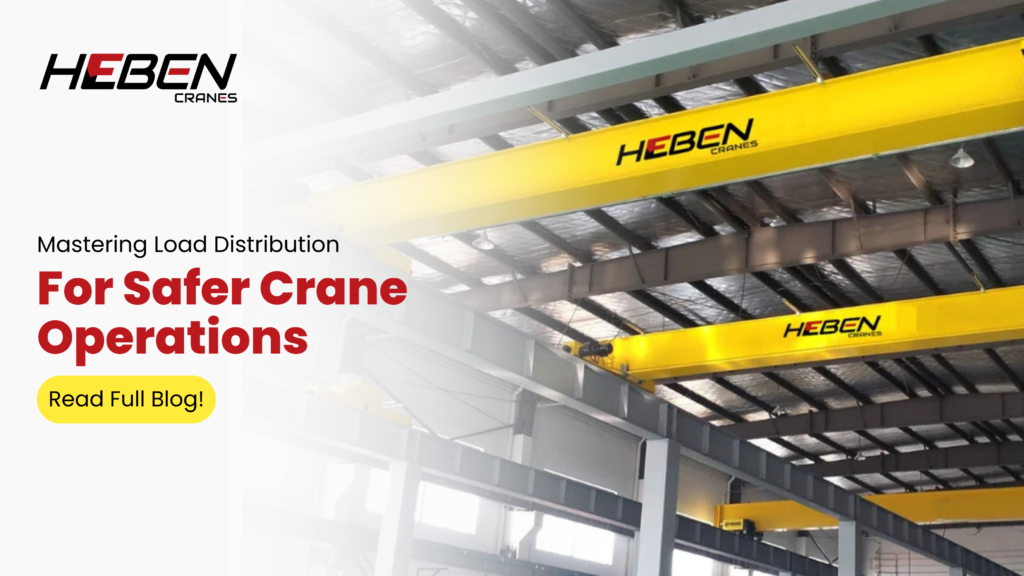
Understanding load distribution is not just a technical necessity; it is a fundamental pillar that ensures safety, efficiency, and reliability. For those zealous about cranes and lifting operations, grasping the subtleties of load distribution can elevate your expertise and enhance your operational practices. This article delves into the significance of load distribution analysis, exploring its core concepts, factors affecting it, techniques for analysis, real-world applications, and best practices. What is Load Distribution? Load distribution refers to how weight is spread across a crane during lifting operations. It is crucial for maintaining stability and preventing accidents. When loads are unevenly distributed, the risk of tipping increases significantly. Incorrect estimations of load weight or distribution can lead to imbalances and potential accidents during crane operations. Types of Loads Understanding the types of loads is essential for effective load distribution analysis: Static Loads: These are loads that remain constant over time. They require careful calculations to ensure that the crane can handle them without risk of failure. Dynamic Loads: These loads change during operation due to factors like movement or environmental conditions. Cranes must be designed to accommodate these variations. Environmental Loads: Wind and seismic activity can impact load stability. Operators must account for these external forces when planning lifts. Factors Affecting Load Distribution Several factors influence how loads are distributed across a crane: Crane Design and Configuration The type of crane plays a significant role in load distribution capabilities. For instance, mobile cranes have different characteristics compared to tower cranes. The design elements such as boom length and angle directly affect how weight is managed during lifts. Load Characteristics The weight and shape of the load are critical in determining its stability. The center of gravity must be accurately calculated; an off-center load can lead to dangerous imbalances. Proper positioning of the load on the crane hook is critical for stability. Load Distribution Analysis Techniques To ensure safe operations, various techniques can be employed for analyzing load distribution: Mathematical Models Mathematical models provide a framework for understanding load behavior under different conditions. One such model is the Gumbel distribution, which helps predict extreme load values based on statistical data. This approach allows operators to anticipate potential risks and make informed decisions. Practical Methods Operators often rely on load charts provided by manufacturers to determine safe lifting capacities. These charts indicate maximum weights based on boom length and angle. Additionally, modern software applications can enhance accuracy by allowing users to input variables such as load weight and environmental conditions for real-time analysis. Real-World Applications Load distribution analysis is not merely theoretical; it has practical implications in various industries: Case Studies Consider a construction project where multiple cranes were used in tandem lifts. A thorough analysis of load distribution helped prevent potential accidents by ensuring that all cranes operated within their safe limits. This kind of proactive planning exemplifies how effective load distribution strategies can enhance safety. Industry Standards and Regulations Adhering to industry standards like those set by OSHA is crucial for maintaining safety in crane operations. These regulations often emphasize the importance of accurate load calculations and proper equipment usage. By following these guidelines, operators can minimize risks associated with improper load management. Best Practices for Effective Load Distribution To achieve optimal load distribution during crane operations, several best practices should be followed: Planning Lifts Creating a comprehensive lift plan is essential. This plan should include detailed assessments of the load’s weight, dimensions, and center of gravity. Operators should also consider environmental factors that may affect stability. Training and Education Continuous training for operators on load distribution principles is vital. Heben Cranes offers resources and training programs designed to keep operators informed about the latest safety protocols and technological advancements in crane operations. Utilizing Technology Incorporating advanced technology into load calculations can significantly enhance safety measures. Real-time monitoring systems provide continuous feedback on weight distribution during lifts, allowing operators to make adjustments as needed. By embracing these innovations, companies can improve their operational effectiveness while ensuring compliance with safety standards. Conclusion Load distribution analysis is a critical aspect of crane operations that cannot be overlooked. By understanding its importance, operators can enhance safety, improve efficiency, and reduce the likelihood of accidents on job sites. As we continue to advance in technology and methodologies within this field, companies like Heben Cranes remain committed to providing high-quality equipment and training that supports safe lifting practices. In summary, mastering load distribution not only safeguards personnel but also optimizes performance in various lifting scenarios. For those passionate about cranes and their operations, delving into this subject will undoubtedly enrich your knowledge base and operational capabilities—ensuring that every lift you undertake is executed with confidence and precision. FAQ Q1: How do I calculate the center of gravity for an irregularly shaped load? To calculate the center of gravity (CoG) for an irregularly shaped load, you can follow a systematic approach that involves weighing and measuring. First, determine the weight distribution by weighing one side of the load (Left End Weight – LEW) and then the other side (Right End Weight – REW). Add these weights to find the total weight of the load. The CoG will shift towards the heavier side. Next, measure the span between the two pick points where you weighed the load. Using the formula (LEW/TW)×span (LEW/TW)×span, where TW is the total weight, you can calculate the position of the CoG along that span. For example, if LEW is 2,000 lbs and REW is 1,000 lbs with a total weight of 3,000 lbs over a span of 100 inches, you would find that the CoG is located closer to the heavier side at approximately 67 inches from one end. This method combines basic mathematics with practical testing to ensure stability during lifting. Q2: Are there any specific certifications or qualifications required for crane operators to conduct load distribution analysis? Yes, crane operators are typically required to have specific certifications and qualifications to conduct load distribution analysis effectively and safely. In India, operators should
Different Types of EOT Crane Configuration

Electric Overhead Travel (EOT) cranes are essential tools in various industries, providing the capability to lift and move heavy loads with precision and efficiency. Understanding the different configurations of EOT cranes can help enthusiasts and professionals alike to choose the right equipment for their specific needs. This article delves into the various types of EOT crane configurations, their applications, advantages, and unique features. What Is EOT Crane Configuration? EOT cranes come in multiple configurations tailored to specific operational needs. The choice of configuration significantly impacts efficiency, capacity, and application suitability. The primary types of EOT cranes include: Single Girder EOT Crane Double Girder EOT Crane Underslung EOT Crane Top Running EOT Crane Gantry Crane Semi-Gantry Crane Jib Cranes (Wall Mounted and Pillar Mounted) Each configuration serves distinct purposes and is designed to meet varying operational requirements. Single Girder EOT Crane The single-girder EOT crane features a single bridge girder supported by end trucks on each side. This design is particularly suited for light to medium-duty tasks. Single Girder EOT Cranes are cost-effective and easier to install, making them a popular choice in smaller manufacturing units. These cranes are commonly used in workshops, warehouses, and manufacturing facilities where space is limited. Their advantages include: Cost-effectiveness: The simpler design reduces manufacturing and installation costs. Space-saving: With a compact structure, they require less vertical clearance compared to double girder cranes. However, they are generally limited in lifting capacity, making them ideal for applications where loads do not exceed 20 tons. Double Girder EOT Crane In contrast, the double girder EOT crane has two bridge girders that provide enhanced strength and load capacity. This configuration is designed for heavy-duty operations, making it suitable for industries such as steel manufacturing and power plants. Double Girder EOT Cranes are designed for heavy-duty operations… commonly used in the steel manufacturing process. The benefits of double girder cranes include: Higher lifting capacities: These cranes can handle loads ranging from 2 to 50 tons or more. Greater span capabilities: They can cover larger areas, making them versatile for various industrial applications. Double girder cranes are often preferred when high precision and strength are required, especially in environments where heavy materials need to be lifted frequently. Underslung EOT Crane Underslung EOT cranes are suspended from the roof structure and run on the bottom flange of the runway girders. This configuration maximizes floor space and is particularly beneficial in facilities with limited headroom. According to Anand Control, “Underslung cranes allow for a more efficient use of the available space in a facility.” The advantages of underslung cranes include: Space efficiency: They utilize existing ceiling girders, eliminating the need for new runway beams. Cost-effectiveness: Typically less expensive than top-running cranes due to lower installation costs. However, underslung cranes generally have a lower capacity range compared to their top-running counterparts. Top Running EOT Crane Top-running EOT cranes feature a fixed rail system installed on top of the building’s support structure. This configuration allows for greater load capacities and is ideal for new construction projects where high headroom is available. As noted by Ganesh Crane, “Top-running configurations do not have any limiting capacity range and can handle both small and huge loads.” Key advantages include: Versatility: Capable of handling heavy loads efficiently. Durability: Designed for long-term use with minimal maintenance. While top-running cranes tend to be more expensive due to installation requirements, their operational benefits often justify the investment. Gantry Cranes Gantry cranes are characterized by their legs that support the bridge structure. These cranes can move on rails at ground level or elevated tracks. They are particularly useful in outdoor settings or where overhead structures are impractical. According to Technomax ME, “Gantry cranes provide flexibility in positioning.” The benefits of gantry cranes include: Mobility: Easily repositioned within a workspace. Large load handling: Suitable for lifting heavy materials across expansive areas. Gantry cranes are commonly used in shipyards, construction sites, and large warehouses where versatility is crucial. Semi-Gantry Cranes Semi-gantry cranes combine features from both gantry and overhead crane designs. They have one leg that runs on a ground track while the other is mounted on an elevated track. This unique setup makes them ideal for specific lifting tasks in confined spaces. The advantages include: Space-efficient design: Ideal for areas where full gantry setups cannot fit. Cost-effective solution: Less expensive than full gantry systems while still offering significant lifting capabilities. Semi-gantry cranes are often utilized in warehouses or workshops where flexibility and space optimization are essential. Jib Cranes (Wall Mounted and Pillar Mounted) Jib cranes extend horizontally from a wall or pillar-mounted support structure. They provide localized lifting capabilities within a specific area, making them perfect for workstations or assembly lines. There are two main types: Wall Mounted Jib Cranes: These save floor space by being attached directly to walls. Pillar Mounted Jib Cranes: Freestanding pillars allow for 360-degree rotation around the column. According to Cranesmith Services, “Jib Cranes provide localized lifting… ideal for workstations.” Their key advantages include: Increased maneuverability: Perfect for tight spaces where traditional overhead systems may not fit. Cost-effective solutions: Generally less expensive than larger crane systems while still providing significant utility. Conclusion Each EOT crane configuration should be understood properly in choosing the right equipment for specific operational needs. Each of these types has its advantages, serving different industries—from manufacturing to construction—with efficient material handling solutions. While choosing an EOT crane configuration, one has to consider some major factors such as lifting capacity, span requirements, operating environment, and budget constraints. By integrating these factors into your operation needs, you will be able to maximize productivity while making sure safety and efficiency are considered in your material handling process.