
Goliath Crane: Features, Applications, and Advantages

Operations that need heavy lifting in open yards, shipyards, or large construction sites face a core problem: conventional EOT cranes need a building with runway beams. No building means no crane. Some facilities add roof structures just to mount a crane — spending significantly more than the crane itself costs. A Goliath crane eliminates this dependency entirely. It stands on its own legs, runs on ground-level rails, and lifts loads that no building-mounted system can reach. This guide covers the structure, performance specifications, applications, and selection factors for Goliath cranes — so you can determine whether this configuration fits your site. What a Goliath Crane Is A Goliath crane is a large gantry crane with structural legs that run on ground-level rails. The bridge girder spans between the two legs. A hoist and trolley travel along the bridge, providing coverage across the full span and rail length. The core distinction from an EOT crane is structural independence. Goliath cranes carry their own loads through the legs to the ground. They don’t transfer forces into a building frame. This makes them the only practical lifting solution for open yards, outdoor sites, and facilities where building construction is not viable. Capacities start at 5 tonnes and extend beyond 500 tonnes. Spans run from 10 meters to over 50 meters depending on the application. Structural Features and Configurations Single Girder vs Double Girder Single girder Goliath cranes use one bridge beam supported by two legs. They handle 5 to 50 tonnes at spans up to 30 meters. Lower structural weight, simpler erection, and lower cost make them suitable for steel stockyards, precast segment yards, and light outdoor handling. Double girder Goliath cranes use two parallel bridge beams with a crab mechanism on top. They handle 50 to 500+ tonnes with spans reaching 50 meters. The twin-beam design gives maximum hook height, higher structural rigidity, and platforms for maintenance access. Leg and Rail System Leg designs are either A-frame or box section: A-frame legs distribute loads across a wider base; suited for standard and heavy duty Box section legs suit ultra-heavy duty and process-critical applications with greater rigidity Ground rails are embedded in concrete foundations. Rail gauge, levelness, and expansion joint spacing must be engineered for span, load, and temperature range. Poor rail alignment is the primary cause of wheel wear, bearing overload, and uneven leg loading on Goliath cranes. Lifting Capacities and Performance Specs Goliath cranes are specified across four motion parameters: Hoist speed: typically 1–8 m/min, lower for heavier lifts Cross-travel speed: 5–20 m/min for trolley movement Long-travel speed: 10–40 m/min for crane movement along rails Duty class: A3 (light outdoor use) to A7 (continuous heavy process duty) Most buyers under-specify duty class on outdoor Goliath cranes. A crane in a steel yard running three shifts needs A6 or A7. An A4 crane in the same application fails within 18–24 months as gearbox and brake components wear through their rated cycles. Advantages Over EOT Cranes The most counterintuitive advantage of a Goliath crane is total installed cost in open-area applications. EOT cranes appear cheaper until you add building structure costs. An EOT crane for an outdoor yard requires a dedicated steel building for the runway. A Goliath crane needs concrete pads and rails. For a 15-tonne outdoor application across 50 meters: Goliath crane total 5-year cost: lower installation cost with simpler maintenance EOT crane equivalent requires building runway — 2–3x higher installation cost Goliath cranes allow relocation; EOT runway structures are permanent Additional structural advantages: No building height restriction on hook height Full outdoor weather resistance with corrosion-resistant coatings and sealed components Tandem operation possible with two cranes on the same rails for wide or heavy loads Safety Features and Compliance Every Goliath crane installation requires these safety components as a minimum: Overload protection via load limiter before structural damage occurs Hoist and travel limit switches to prevent rope overrun and end-of-rail collision Dual brakes on all motions — hoist, cross-travel, long-travel Anti-collision systems for multi-crane yards operating on shared rail systems Rail sweeps and derailment guards on all end trucks Wind load design for outdoor cranes: structural calculations include wind forces at the installation site IS, FEM, and CMAA standards govern design, load testing, and operational compliance. Statutory load testing at 125% rated capacity is mandatory before commissioning. Typical Applications Goliath cranes operate across sectors where building-mounted systems are impractical: Shipyards: ship section assembly, block erection, hull component handling Bridge construction: precast beam handling, segment placement, formwork moving Steel stockyards: slab, billet, coil stacking and unstacking in outdoor storage Heavy fabrication: large structural assemblies, pressure vessels, transformer bodies Precast yards: column, beam, slab handling for construction material producers A common pattern: facilities that start with a mobile crane for outdoor yard work switch to a Goliath crane once throughput demands exceed what a mobile crane can cycle through efficiently. Installation and Site Preparation Installation sequence follows five stages: Foundation works: concrete pads, rail anchors, expansion joints, drainage Rail laying: rail alignment within ±3 mm gauge tolerance over full length Leg and girder erection: mobile cranes lift leg assemblies; girder sections splice and bolt at height Electrical installation: busbar or cable reel for long-travel power, panel commissioning Testing and commissioning: no-load trials, load testing at 125%, limit switch calibration, brake verification Site preparation is the most time-consuming phase. Foundation concrete must cure for a minimum of 28 days before rail installation. Rushing this stage causes rail settlement, track gauge deviation, and crane misalignment within six months of commissioning. FAQs Can a Goliath crane be relocated to a different site? Yes. Goliath cranes are designed for disassembly and relocation. Legs, girder sections, and rails can be unbolted, transported, and re-erected at a new site. New foundation works are required at the new location. This relocatability is a key advantage over building-mounted EOT systems, which are permanent once installed. What is the difference between a Goliath crane and a semi-Goliath crane? A full Goliath crane has two ground-level legs running on floor rails
Top Industries That Benefit from Jib Crane Installation
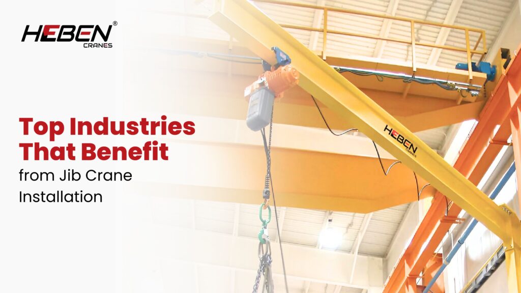
Facilities install overhead cranes for wide-area coverage, then discover 40% of daily lifts happen within a 3-5 meter radius at individual workstations. Overhead cranes don’t solve this. Workers improvise with forklifts, manual handling, or awkward rigging—creating bottlenecks, injuries, and slow cycle times. Jib cranes solve localized lifting precisely. A single pillar-mounted or wall-mounted unit covers one workstation, one machine, one loading bay—with full 180-360° rotation and capacities from 250kg to 5 tons. This guide covers the industries where jib cranes deliver the clearest operational improvement, the specific applications driving that value, and the selection factors matching crane type to task. Manufacturing and Assembly Lines Assembly operations produce the clearest jib crane case. Components move between stations repeatedly. Each move is short, specific, and time-critical. A jib crane mounted at each station handles this without competing for shared overhead crane time. Welding bays use jib cranes to position heavy sub-assemblies for flat or positional welding. The operator rotates the arm, positions the load, and locks it in place. Jig and fixture handling follows the same pattern. Cycle times drop when operators control their own lifting resource rather than waiting for a shared crane. The contrarian insight: most plants install one overhead crane covering the full floor, then discover workstation congestion from crane sharing. Adding jib cranes at high-frequency stations costs less than a second overhead crane and solves the bottleneck more directly. Warehousing and Logistics Loading bays present a specific lifting problem. Loads arrive and depart at fixed points. Coverage radius is small. Speed matters. A wall-mounted jib crane at each bay handles goods movement without forklift congestion in tight dock areas. Conveyor feed stations use jib cranes to transfer heavy bags, drums, and boxes from floor level to conveyor height. The short, repetitive nature of this task suits jib crane geometry exactly. Operators handle the lift in seconds rather than repositioning handling equipment. Mezzanine loading points benefit from column-mounted jib cranes serving both floor and upper levels. One unit covers the vertical transfer zone. No overhead crane access is needed at these locations. Automotive and Aerospace Engine assembly requires precise component positioning over close tolerances. Jib cranes mounted at engine build stations handle block and head positioning, gearbox mating, and ancillary component installation. The operator controls movement directly, placing components within millimetres. Body shop operations use jib cranes for panel handling, door fitting, and sub-frame positioning. These are short-range, high-frequency lifts at fixed workstations. The alternative—manual handling of 50-200kg panels—creates ergonomic injuries and quality problems from surface contact damage. Aerospace component handling demands both capacity and precision. Turbine blades, actuator assemblies, and avionics packages weigh 20-300kg. Jib cranes with fine-speed hoists handle these components without the shock loading risk of manual movement. Construction and Fabrication Yards Fabrication shops use jib cranes at cutting tables, press brakes, and welding positions. Plate and section steel weighs 80-500kg per piece. Manual handling at these weights creates injury risk and slow production. A jib crane at each machine removes both problems. Outdoor construction sites use pillar-mounted or portable jib cranes for rebar cage assembly, precast element handling, and formwork positioning. The freestanding pillar design requires no building attachment, making it suitable for open site locations. Steel service centres handle cut-to-length sections and rolled product with jib cranes at slitting and shearing lines. The crane serves the machine directly. Material flow from process to stacking position covers 3-6 meters—exactly the range where jib cranes outperform all alternatives. Power and Energy Sector Transformer installations require precise positioning in confined electrical switchrooms. Overhead cranes can’t always access these locations. A wall-mounted jib crane inside the switchroom handles transformer positioning during installation and maintenance replacement. Turbine maintenance bays use jib cranes for blade removal, bearing replacement, and ancillary equipment handling. Maintenance cycles repeat at fixed intervals. A permanent jib crane installation at each maintenance bay eliminates mobile crane hire for every service event. Generator and motor repair facilities handle rotors, stators, and end shields weighing 100-2,000kg. Jib cranes at repair benches handle these components through disassembly, inspection, and reassembly sequences. The fixed-position crane serves the workstation throughout each repair cycle. Machine Shops and Maintenance Facilities CNC machining centres require workpiece loading and unloading for every job. Parts weigh 20-500kg. A jib crane mounted at each machine handles this independently. Machine operators don’t wait for overhead crane availability. Cycle time is determined by machining, not material handling. Typical Machine Shop Applications Workpiece loading onto CNC turning, milling, and grinding machines Fixture and tooling movement between storage and machine Finished part transfer from machine to inspection table Heavy chuck and collet handling at lathe positions Maintenance workshops use jib cranes for equipment disassembly and rebuild. Pump casings, gearbox housings, and motor frames move between floor and workbench positions repeatedly during overhaul. A jib crane rated 500kg-2 tons covers most maintenance workshop lifting requirements. Food and Beverage Processing Ingredient handling in food production involves bags, drums, and intermediate bulk containers weighing 25-1,000kg. Jib cranes at mixing and batching stations lift and tip these containers directly into process vessels. The alternative—manual bag handling—creates musculoskeletal injury and contamination risk simultaneously. Hygienic design variants use stainless steel construction and sealed bearings for washdown environments. Food-safe coating systems meet FDA and HACCP requirements. These features add cost but eliminate contamination risk that standard crane finishes can’t address. Packaging line infeed stations use jib cranes to load bulk materials onto conveyors. The short transfer distance and fixed position suit jib crane geometry directly. Installation at each infeed point removes manual handling from a task performed hundreds of times per shift. Shipbuilding and Marine Repair yards use wall-mounted jib cranes along dry dock walls for tooling, equipment, and small component handling. The crane reaches over the vessel side. Marine service technicians work independently without competing for yard overhead crane time. Engine room access is confined and awkward. Jib cranes positioned at engine room hatches lower and raise tools, replacement parts, and removed components through the access opening. The controlled movement reduces damage to both equipment and
Types of EOT Cranes: Complete Guide to Overhead Lift Systems
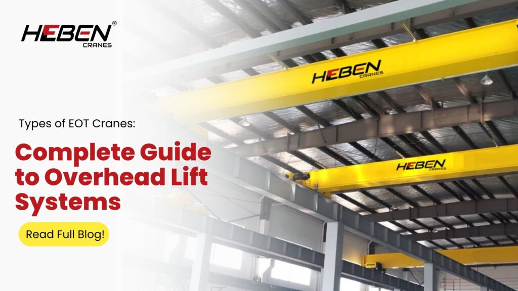
Introduction Your facility needs an overhead crane, but the configuration options are wider than most buyers expect. Choosing the wrong type means structural modifications you didn’t plan for, capacity limits that stop production, or headroom problems discovered only after installation. EOT (Electric Overhead Travelling) cranes cover a full range of configurations — from single girder workshop units to heavy double girder systems for steel plants. This guide breaks down each type, its specifications, application range, and the selection logic that matches crane configuration to your load patterns, bay dimensions, and duty requirements. Single Girder EOT Cranes Single girder cranes use one bridge beam with the hoist trolley running along the bottom flange. The design is compact and cost-effective for light to medium duty applications. End carriages at both beam ends travel on runway beams mounted to building columns. Capacity ranges from 0.5 to 20 tons, with spans covering 5 to 30 meters. Duty classes A3 to A4 suit 2–4 hours of daily intermittent operation. Runway beams are lighter and column reinforcement is minimal compared to double girder alternatives, which reduces total project cost. Double Girder EOT Cranes Double girder cranes use two parallel bridge girders with the hoist trolley traveling on rails mounted between them. The hoist sits between girder tops rather than hanging below a single beam, which increases hook-to-floor distance significantly. Capacity spans 5 to 250+ tons with bridge spans up to 60 meters. Duty classes A5 to A7 serve continuous heavy operation in steel plants, automotive facilities, and power plants. The structural rigidity distributes loads evenly across runway beams, reducing wheel loads and extending rail life. Here’s the counterintuitive reality: facilities often over-invest in double girder cranes for loads under 20 tons. A correctly specified single girder system costs 30–40% less and handles the same operational requirement without excess structural overhead. Underslung EOT Cranes Underslung cranes suspend the bridge from the bottom flange of runway beams rather than riding on top. The hoist hangs below the bridge, which hangs below the runway. The entire crane occupies the lower portion of the building. Capacity limits sit at 1–10 tons for single girder underslung systems, with double girder versions reaching 20 tons. Spans typically range from 3 to 15 meters. Many installations use existing roof structure, avoiding new column work and dramatically reducing installation cost and timeline. Underslung cranes recover 1–2 meters of hook travel that top-running systems lose to structural depth. In a 4.5-meter ceiling building, this difference determines whether the crane is operationally useful or structurally limited. Gantry and Semi-Gantry EOT Cranes Gantry cranes use legs that travel on ground rails instead of building-mounted runways. The bridge spans between these self-supporting legs. Full gantry cranes operate completely independent of building structure — suitable for outdoor yards and facilities without roof support. Semi-gantry cranes run one leg on a ground rail while the other side travels on a building runway. Capacity ranges from 1 to 50 tons across spans up to 35 meters. This configuration suits facilities with partial structural support on one bay side. Gantry cranes cost 20–35% more than equivalent EOT systems where adequate building structure already exists. Choose gantry for outdoor yards or buildings with inadequate columns — not as a default alternative to top-running EOT. Jib Cranes Jib cranes mount to a wall, pillar, or freestanding column and rotate through a horizontal arc. Wall-mounted versions fix to building columns. Pillar-mounted types use independent freestanding columns with engineered foundations. Capacity ranges from 0.5 to 10 tons with outreach up to 10 meters. Rotation spans 180–360 degrees depending on mounting type. Jib cranes suit workstation lifting where loads move through fixed arcs rather than across full bay lengths. Multiple jib cranes create coverage patterns that linear EOT systems can’t match cost-effectively in assembly-intensive workshops. They function best as complements to main EOT systems, not replacements. Key Components Across All Types Every EOT configuration shares a common set of functional components: Bridge girder(s): Main structural span carrying trolley and load End carriages: Contain wheels, drive motors, and brakes for runway travel Hoist and trolley: Vertical lifting and lateral cross-travel Control system: Pendant push buttons, radio remote, or cabin operation Safety devices: Overload protection, limit switches, emergency stops, anti-collision systems Electrical panel: Motor controls, variable frequency drives, circuit protection Wire rope hoists suit heavy continuous lifts. Chain hoists work for lighter precision applications. Duty class ratings define operating intensity across all configurations. How to Select the Right EOT Crane Type Step 1: Calculate Load and Duty Document maximum load, typical operating load, and lifts per shift. Calculate duty class from actual frequency data, not assumed maximum. Duty class mismatch causes 60% of premature failures — it’s the most underweighted specification in most buying decisions. Step 2: Measure Bay Constraints Measure clear span between runway support columns and available headroom. Single girder suits spans up to 30 meters. Double girder extends to 60 meters. For headroom under 5 meters with loads below 10 tons, underslung is the practical answer. Step 3: Assess Building Structure Confirm column and roof beam capacity for your crane type. Top-running EOT cranes require dedicated runway beams with column reinforcement. Underslung cranes transfer loads through existing roof structure — structural verification is mandatory before specifying. Step 4: Choose Control and Safety Specifications Select operation method based on operator visibility and cycle complexity. Pendant controls suit simple repetitive tasks. Radio remotes improve positioning accuracy when operators move with the load. Cabin control applies to high-volume continuous operations. Step 5: Plan for Service and Expansion Specify future capacity scenarios before ordering. Double girder systems accommodate hoist upgrades. Single girder cranes rarely convert to higher capacity without complete replacement. Build service access and maintenance platform provisions into the design, not as afterthoughts. Frequently Asked Questions What’s the practical capacity limit for single girder EOT cranes? The standard ceiling is 20 tons. Beyond this, deflection and structural demands make double girder configurations more economical. Some manufacturers quote 25 tons, but runway and column costs at that capacity make
Leading Underslung Crane Manufacturers: Industrial Solutions
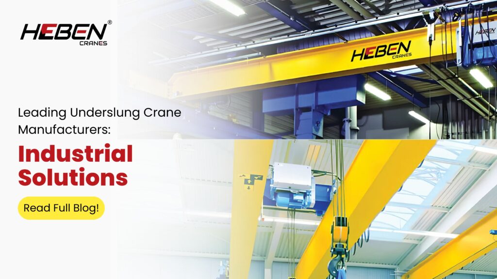
Introduction Choosing the wrong underslung crane manufacturer costs you twice—once in money, once in downtime. Maharashtra’s industrial facilities rely on underslung cranes for low-headroom applications, yet many buyers select suppliers based on price alone, only to face delayed deliveries, substandard quality, or vanished after-sales support. The truth? A manufacturer’s fabrication capability, service infrastructure, and proposal transparency determine whether your crane operates reliably for 15-20 years or becomes a maintenance burden within 3-5 years. This guide separates qualified suppliers from problematic ones by examining manufacturing depth, regional expertise, service commitments, and the questions that reveal true capability. Understanding Underslung Crane Design An underslung crane suspends from the bottom flange of runway beams instead of sitting on top, reversing the load path compared to top-running systems. This configuration suits facilities with 3-4 meters of headroom where traditional cranes cannot fit. The trolley travels along the underside of the bridge girder, with the hoist hanging below. Typical applications include light manufacturing assembly lines, warehousing storage retrieval, and retrofit projects where building structure cannot support top-running loads. Capacities range from 1 to 12.5 tons, with spans reaching 22.5 meters—though most installations stay under 15 meters for optimal structural efficiency. Here’s the counterintuitive reality: underslung systems often cost 40-60% less to install than equivalent top-running cranes, not because of cheaper components, but because they skip runway beam installation and structural reinforcement. The savings come from faster assembly and utilizing existing building beams as runways. Criteria for Leading Manufacturers Manufacturing Capability vs. Trading Operations Leading manufacturers operate in-house fabrication facilities with certified welders, CNC cutting equipment, and load testing rigs. Trading companies merely broker products, controlling neither quality nor delivery timelines. Request a facility visit to observe welding quality and stage-wise production—genuine manufacturers welcome this; brokers make excuses. Compliance and Certification Benchmarks Indian Standard IS 3177 governs crane design and manufacturing. Top suppliers provide material traceability certificates, IS 3177 compliance verification, and third-party test reports from agencies like Lloyd’s or Bureau Veritas. ISO 9001 certification indicates systematic quality management—non-negotiable for industrial suppliers. Customization for Building Constraints Standard catalogue products rarely match facility requirements perfectly. Leading manufacturers engineer solutions for specific span lengths, lifting heights, and existing beam configurations. They assess whether your ceiling beams can support suspension loads without reinforcement—a critical step many skip. Regional Manufacturer Landscape in India Pune Industrial Corridor Pune dominates automotive component manufacturing and precision engineering. Suppliers here specialize in higher duty cycles, integration with automated lines, and clean-room compatible variants for pharmaceuticals. The concentration of automotive plants drives demand for variable frequency drives and soft-start systems. Mumbai and MMR Mumbai suppliers serve port logistics, textile mills, and light manufacturing. Emphasis falls on compact designs for space-constrained facilities and rapid delivery to meet port operation schedules. Thane and Navi Mumbai host numerous fabrication units offering both standard and custom configurations. Ahmedabad and Gujarat Belt Ahmedabad serves as a hub for chemical, engineering, and textile industries. Suppliers here excel in corrosion-resistant coatings for chemical environments and explosion-proof configurations for hazardous areas. The region’s export-oriented manufacturers often maintain global-standard quality practices. Chennai and South India Chennai suppliers focus on heavy engineering, railways, and automotive sectors. Strengths include large-span expertise and experience with foundation engineering for outdoor installations. National players with pan-India service networks operate from these regions. Features of Top Underslung Crane Systems Structural Efficiency Top systems use Grade IS 2062 structural steel, stress-relieved after welding to prevent residual stresses that cause premature failure under cyclic loading. Girder dimensions optimize weight-to-strength ratio—oversized girders waste material; undersized ones deflect excessively. Hoisting and Control Quality European-standard hoists (0.5-5 ton capacity) or robust Indian-made units for heavier loads determine long-term reliability. Control systems featuring Schneider or Siemens components with proper IP ratings reduce electrical failure rates significantly. Overload protection and emergency stops are non-negotiable safety features. Headroom Optimization True underslung design minimizes additional height beyond the hoist itself. The trolley runs on the bottom flange of the girder, keeping the crane profile low. Facilities gain 150-250mm of effective lifting height compared to top-running alternatives in the same building envelope. Wire Rope vs. Chain Hoist Selection Wire rope hoists suit 1-ton+ capacities and longer lift heights with higher speeds. Chain hoists excel in compact applications under 5 tons with lower lift heights—common in maintenance bays and workshops. The choice affects both initial cost and long-term maintenance patterns. Services Offered by Leading Suppliers Engineering and Design Depth Qualified suppliers conduct structural assessments before quoting—not just accepting your capacity and span at face value. They verify whether existing beams can support suspension loads, propose reinforcements if needed, and provide load calculations for foundation design where ground rails are required. Installation and Commissioning Excellence Installation teams include structural engineers who verify building support adequacy, not just riggers who bolt equipment in place. Commissioning involves operator training, safety protocol development, and complete documentation handover—suppliers treating these as optional extras create operational gaps. After-Sales Support Infrastructure Regional service infrastructure determines recovery speed from breakdowns. Top suppliers maintain local spare parts inventory for critical components—brake pads, limit switches, wire ropes—and guarantee 24-48 hour emergency response. Annual maintenance contracts prevent slow degradation that leads to sudden failures. How to Choose the Right Manufacturer Essential Verification Checklist Request proof of in-house fabrication (facility visit invitation) Verify IS 3177 compliance and material traceability documents Confirm regional service presence with response time commitments Review warranty terms: structural (24 months), mechanical (12 months), electrical (12 months) Ask for three recent client references in your industry with facility visit options Critical Questions to Pose “Can you show me your load testing procedure and certification documents?” “What specific checks do you perform on suspension points during installation?” “How do you handle cases where existing beams require reinforcement?” “What’s your spare parts commitment period for this crane model?” “Who performs the annual comprehensive inspection—your team or third party?” Red Flags That Signal Problems Suspiciously low quotes (30% below market) usually mean substituted materials or hidden installation exclusions. Vague delivery commitments without manufacturing schedules suggest outsourced production the supplier cannot control. Reluctance
Types of Jib Cranes: Industrial Guide

Most factories solve workstation lifting the wrong way. They route every pick through the main overhead crane. The EOT crane moves a large assembly. Meanwhile, a machinist waits to load a 400 kg fixture. A welder needs a component from the rack. An assembler needs a part shifted half a meter. The main crane handles one job at a time. Everyone else waits. A jib crane at each workstation breaks this dependency entirely. This guide covers every major jib crane type — design, rotation, capacity, and application — so you can select the right configuration for each location in your facility. What Jib Cranes Do A jib crane consists of a vertical support, a horizontal boom, and a hoist that travels along the boom. The boom rotates around the support, creating a fixed circular lifting zone. Each crane serves one workstation independently. Capacities range from 125 kg to 15 tonnes. Boom lengths run from 2 meters to 15 meters. Rotation angles vary from 180 degrees on wall-mounted types to full 360 degrees on floor-mounted types. The core advantage is decentralization. Jib cranes give each station its own lifting capacity without competing for the main crane. Pillar Mounted Jib Cranes A pillar jib crane stands on an independent steel column fixed to a concrete foundation. The boom rotates 360 degrees around the column. This covers all four quadrants around the mast — effectively serving multiple adjacent workstations. Capacities reach up to 10 tonnes with boom lengths of 3 to 12 meters. The foundation carries all structural loads independently. Building columns and roof structure are not involved. Pillar jibs are the most structurally reliable type for medium to heavy loads. Their load path — mast to baseplate to foundation — is direct, predictable, and easy to engineer. Wall Mounted Jib Cranes A wall-mounted jib crane fixes to a building wall, structural column, or bracket. The boom rotates 180 to 270 degrees, depending on the mounting angle. No floor space is occupied. No foundation is required beyond the existing column or wall. Capacities for wall jibs typically stay under 2 to 5 tonnes with booms up to 8 meters. The mounting point must carry the full bending moment of the boom under rated load. Older industrial buildings with undersized columns fail this check more often than buyers expect. The practical rule: wall jibs suit light loads on strong columns. When capacity exceeds 2 tonnes or boom length exceeds 6 meters, a structural assessment is mandatory before installation. Free Standing Jib Cranes A free standing jib crane uses a self-supporting mast without wall or roof attachment. The mast bolts to a floor base plate or embedded sleeve. The boom gives full 360-degree coverage. Capacities reach up to 15 tonnes with booms extending to 12 meters or more. Free standing jibs work indoors and outdoors. They suit loading docks, outdoor yards, and open bays where no building structure exists nearby. The installation is flexible. The crane positions anywhere a concrete pad can be poured. This makes free standing jibs the preferred choice for new facility layouts and outdoor handling areas. Articulating Jib Cranes An articulating jib crane uses two boom segments — an inner arm and an outer arm — each rotating independently. The outer arm rotates 360 degrees. The inner arm adds a second rotation axis. Together, they reach into corners, around obstacles, and into confined machine openings that a straight boom cannot access. Capacities stay light — typically under 1 tonne with combined reach up to 5 meters. Articulating jibs suit precision assembly, instrument handling, and machine loading where the load path requires two-axis maneuvering. The unexpected insight: 70% of articulating jib applications are not about reach — they’re about avoiding collisions with machine guards, fixtures, and adjacent equipment that a rigid boom would hit on every cycle. Mast Type Jib Cranes A mast type jib crane is supported at the base by the floor and at the top by the building’s overhead structure. The top tie removes the overturning moment from the foundation. This reduces foundation size and cost compared to a fully free standing mast. Capacities reach up to 10 tonnes with boom lengths of 3 to 12 meters. The overhead tie point must be structurally verified. But the load is primarily vertical tension, not bending — making it easier to integrate with existing roof purlins and rafters than an underhung crane runway. Mast jibs suit facilities where floor space is limited and the roof structure can carry vertical tie loads without major reinforcement. Portable and Mobile Jib Cranes A portable jib crane uses a ballasted base or wheeled chassis for relocation. It serves temporary lifting needs — maintenance access, site installation, equipment repositioning. Capacities stay below 1 to 2 tonnes. Mobile jibs give 360-degree rotation and require no permanent fixing. They are not substitutes for fixed workstation cranes in production environments. Frequent relocation creates repositioning time and reduces the productivity gain that fixed jibs deliver on a per-shift basis. Key Features Across All Jib Types Regardless of type, every jib crane includes these core features: Hoist options: electric chain hoist, wire rope hoist, or manual chain fall Rotation mechanisms: manual push-pull, motorized with brake, or lockable fixed positions Safety devices: overload protection, limit switches for hoist travel, rotation stops Special executions: low headroom units for restricted bays, corrosion-resistant coatings for outdoor or coastal environments, flameproof and ATEX certified versions for hazardous areas How to Select the Right Jib Crane Follow these four steps to match the crane type to the application: Define load and reach: confirm maximum lift weight, boom radius required, and hook height needed at the workstation Assess the building: check floor strength for foundation, column capacity for wall mounting, roof structure for tie loads Match duty cycle: count lifts per shift and estimate daily operating hours; this determines hoist duty class and rotation mechanism type Plan for installation and expansion: confirm site access for foundation work, allow clearance for boom rotation, and check interference with overhead
Top Goliath Gantry Crane Manufacturers: Industrial Guide
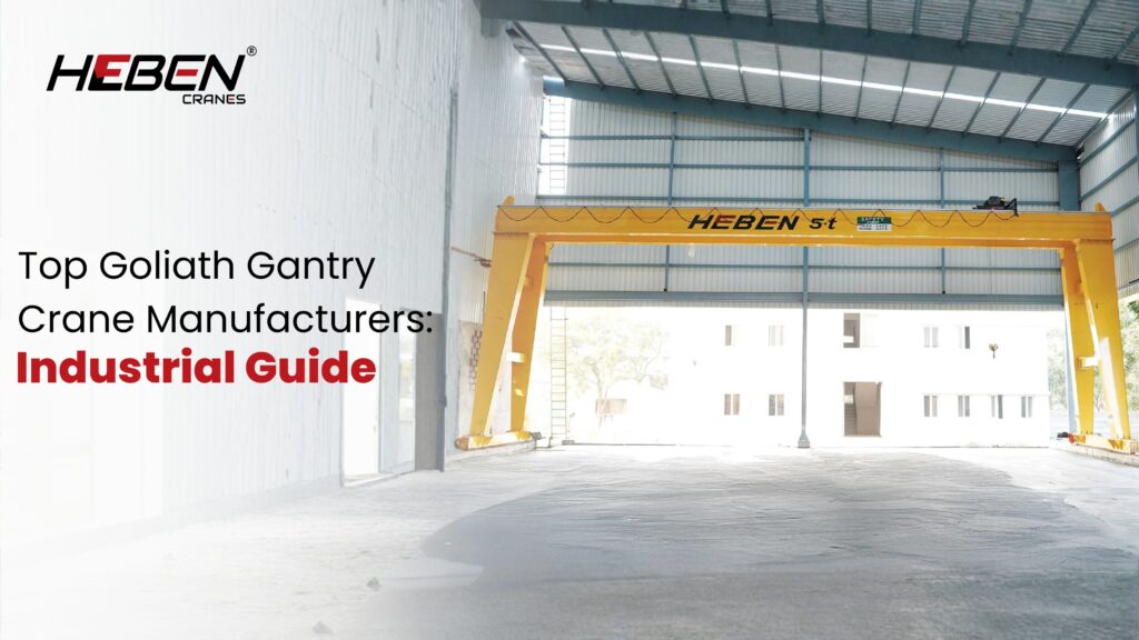
Goliath gantry crane procurement fails most often not at the specification stage but at the supplier selection stage. Facilities invest months developing load and span requirements, then choose manufacturers based on price alone—ignoring fabrication quality, engineering depth, after-sales infrastructure, and service network reach. The result: cranes delivered late, misaligned on site, or unsupported during breakdowns. A reliable Goliath crane manufacturer brings engineering expertise, proven project delivery, quality-controlled fabrication, and long-term service capability. This guide covers crane types, key manufacturer features, selection criteria, industry applications, cost and maintenance realities, and the practical checklist separating capable suppliers from sales operations. What Are Goliath Gantry Cranes? Goliath gantry cranes are rail-mounted heavy-duty lifting systems supported by two structural legs running on ground-level tracks. The bridge spans between the legs. A hoist and trolley system travels across the bridge. The entire structure rides rails installed at yard or facility floor level. Capacities start at 50 tons and scale beyond 1,000 tons for shipbuilding and offshore construction applications. Spans routinely exceed 100 meters in large shipyard installations. This scale separates Goliath cranes from standard gantry designs in both engineering complexity and manufacturer requirements. The design suits outdoor heavy industrial environments where overhead building structure cannot support the required loads. Shipyards, steel yards, container terminals, and precast concrete facilities are the primary users. Types and Configurations Single girder Goliath cranes handle 10-50 ton capacities for medium-duty outdoor applications. The lighter structure reduces foundation costs but limits span and duty class. Double girder configurations carry 50-1,000+ tons across long spans with A6-A8 duty ratings. Portal Goliath cranes use full two-leg structures supporting the bridge at both ends. Semi-Goliath designs support one end on a ground rail and the other end on an elevated runway beam attached to building structure. Semi-Goliath suits facilities where one wall can carry the load, reducing full portal foundation requirements. Specialised types include U-frame designs for low-headroom applications, container handling RMG (Rail Mounted Gantry) variants, and shipbuilding configurations with tandem hoist systems for 500-1,000+ ton lifts. Key Features to Evaluate Structural engineering quality determines how the crane performs under sustained heavy service. Evaluate girder design, leg-to-girder connection details, and rail attachment systems. Poorly detailed connections fatigue early under dynamic loads and require expensive field repairs. Control and drive systems define operational precision. Variable frequency drives on all three motions—hoist, trolley, and bridge—provide smooth acceleration, precise positioning, and energy recovery during lowering. Anti-sway technology reduces load oscillation for faster cycles and safer positioning. Safety systems must include, at minimum: Hoist overload protection with automatic cut-off End travel limit switches on all axes Emergency stop systems accessible from cabin and ground Collision avoidance for multi-crane runway installations Manufacturer Selection Criteria Engineering depth separates manufacturers from assemblers. A capable manufacturer employs structural engineers, electrical engineers, and commissioning specialists in-house. Request evidence—project drawings, structural calculation reports, test certificates—not just capability brochures. Manufacturing facility capacity matters for large Goliath projects. Fabricating a 200-ton, 80-meter span crane requires heavy fabrication bays, large overhead cranes for sub-assembly handling, precision welding capability, and full-load test infrastructure. Verify these exist before awarding contracts. Quality management certification (ISO 9001) demonstrates systematic process control. Standards compliance—FEM, CMAA, or IS specifications depending on geography—confirms the crane is designed to recognised fatigue and load calculation methods. Ask which specific standards govern the design and request documentation. The contrarian insight most procurement teams miss: manufacturers quoting 20-30% below market rates rarely achieve this through efficiency. They achieve it through thinner plate sections, reduced weld quality, lighter rail systems, or absent post-delivery service. The savings appear at purchase and disappear within five years of operation. Industry Applications Shipyards use Goliath cranes spanning dry docks and assembly areas. Block assembly lifts reach 300-500 tons. Tandem crane operations combine two units for single lifts exceeding individual rated capacities. Accuracy requirements are millimetre-level during hull assembly. Steel mills handle coils, billets, structural sections, and scrap with Goliath cranes in outdoor storage yards. A7-A8 duty classifications apply. Cycle rates run 30-50 lifts per hour across continuous multi-shift operations. Crane downtime directly halts production. Container terminals use Rail Mounted Gantry variants for stacking containers. Automation integration handles 40-65 moves per hour with minimal operator input. Position accuracy and cycle speed drive terminal throughput. Power plant construction requires Goliath cranes for turbine installation and reactor component handling. Single lifts reach 150-400 tons during construction phases. Precision and load control are critical during reactor and turbine positioning. Cost, Installation, and Maintenance Total ownership cost extends well beyond equipment price. Foundation and rail system design, site preparation, rail installation, and electrical supply infrastructure add 30-60% to equipment cost in typical installations. Budget these early. Installation complexity scales with crane size. Goliath cranes arrive in sections. Field assembly, alignment, and load testing require specialist teams and extended site programmes. Manufacturers with dedicated commissioning engineers reduce risk during this phase. Maintenance for A7-A8 duty cranes runs monthly detailed inspections and quarterly comprehensive assessments. Spare parts availability determines how quickly breakdowns resolve. Manufacturers maintaining parts inventory and regional service support minimise downtime when components fail. Emerging Manufacturing Trends Automation integration shifts Goliath cranes toward semi-autonomous and fully autonomous operation in high-throughput facilities. Container terminals lead this adoption. Shipyards and steel mills follow with semi-automated positioning systems reducing operator workload during precision lifts. Energy recovery through regenerative drive systems captures braking energy during load lowering and bridge deceleration. High-cycle operations recover 15-25% of total energy input. Manufacturers offering regenerative capability deliver measurable operating cost reductions in continuous-duty applications. Modular construction techniques allow faster site assembly and reduce field welding requirements. Bolted splice connections replace field welds at key structural joints. Quality control improves and assembly time shortens. Frequently Asked Questions How do I verify a manufacturer’s project delivery track record? Request a project reference list with contact details for clients operating cranes of similar capacity and span. Visit operating sites when possible. Check delivery dates against contracted dates and ask about post-delivery service experience. Manufacturers with genuine track records provide verifiable references without hesitation. What foundation requirements do Goliath
Difference Between Underslung Crane and EOT Crane: A Guide
Introduction Your facility needs an overhead crane, but two fundamentally different configurations are on the table. Choosing the wrong one means structural modifications you didn’t budget for, capacity limits you’ll hit within a year, or headroom problems that ground the system before it starts. EOT cranes run on top of runway beams and scale from 10 tons to 500+ tons across long spans. Underslung cranes suspend from the bottom flange of beams and suit compact, low-headroom spaces up to 20 tons. This guide covers structural differences, capacity ranges, installation demands, maintenance factors, and a five-step selection process to match crane type to your actual facility conditions. What is an EOT Crane An EOT (Electric Overhead Travelling) crane positions its bridge on top of dedicated runway beams mounted to building columns. End carriages ride along the top surface of these beams. The hoist and trolley assembly sits above runway level, which maximises the distance between hook and floor. Single girder EOT cranes handle loads up to 20 tons. Double girder configurations support 20–500+ tons across spans up to 45 meters, with the hoist trolley mounted on rails between two parallel beams. This design scales systematically — capacity increases drive structural upgrades, not configuration changes. Duty classes from A3 to A7 define operating intensity. EOT cranes are the default choice in Indian manufacturing plants because the infrastructure investment supports both current loads and future capacity increases without replacing the crane. What is an Underslung Crane An underslung (underhung) crane suspends its bridge from the bottom flange of runway beams. The hoist hangs further below the bridge. The entire crane occupies the lower portion of the building, working within headroom that a top-running EOT system cannot use. This configuration suits facilities with ceiling heights of 3.5–5 meters where top-running installation is structurally impractical. Many underslung cranes mount to existing roof beams without new columns or major structural work. Installation proceeds faster and with less disruption to active production floors. Practical capacity limits sit at 10–20 tons for standard industrial underslung systems. Beyond this threshold, suspension loads strain standard roof structures and the engineering complexity exceeds the headroom benefit. Structural Differences The difference in load path is the defining distinction. EOT cranes direct vertical and horizontal forces down through columns via engineered runway beams. The structure is purpose-built for crane loads. Underslung cranes transfer loads through existing roof beams via suspension points. The roof structure, not dedicated columns, carries the crane. Headroom consumption divides the two types sharply. A top-running EOT crane adds minimal depth between runway beam top and full-height hook position. An underslung crane adds beam depth, bridge depth, hoist depth, and suspension clearance before the hook begins its travel. In a 5-meter clear height building, this stack can reduce usable hook travel by 1.2–1.8 meters compared to a top-running system. Girder and end carriage mounting differ accordingly. EOT end carriages use wheels on beam top surfaces. Underslung end carriages use wheels on beam bottom flanges, which limits load rating because standard I-beam flanges aren’t designed for high concentrated loads at the flange edge. Capacity and Span Capabilities EOT cranes dominate applications from 10 tons upward. Double girder systems serve steel mills, auto plants, and power facilities where 50–200 ton lifts happen across multiple shifts. The structure scales because dedicated runways absorb increasing loads systematically. Underslung cranes cover light to medium applications under 10–20 tons. Multiple underslung units can share common runway beams, creating flexible multi-zone material flow that a single EOT system can’t replicate cost-effectively in tight workshops. Here’s the pattern most plant engineers overlook: facilities with sub-10-ton needs default to EOT cranes and pay for column reinforcement and new runways they didn’t need. Underslung cranes handle the majority of light industrial lifting requirements at lower installation cost when existing roof structure is adequate. The default choice isn’t always the right choice. Installation Requirements EOT installation demands engineered runway beams fixed to columns at precise elevations. Alignment within 3–5mm across full span prevents bridge skew and wheel wear. Column reinforcement adds 15–25% to total project cost in older facilities. Underslung systems mount to existing roof beams or new mono-rail supports in many cases. Installation is faster and less disruptive. Some facilities install underslung cranes above active production floors without stopping operations. The cost difference narrows when building structure requires significant upgrading for underslung loads. Always get a structural engineer to verify existing beam capacity before specifying underslung configuration. The assessment cost is negligible against the cost of discovering inadequate structure during installation. Maintenance and Operation EOT cranes concentrate wear on wheels, rails, and drive components due to higher loads and top-running contact forces. Access to end trucks and drive motors happens from maintenance walkways at runway level. Scheduled servicing is typically monthly for drive components at higher duty classes. Underslung cranes offer better lateral maneuverability in confined bays. The suspended bridge self-centres through minor runway misalignments better than top-running wheels. Maintenance access requires working at height from ladders or mobile platforms, which adds time to routine servicing. Bottom flange wear is specific to underslung systems. Wheel contact on the flange’s lower surface creates wear patterns that require periodic rail inspection. Flange width must match wheel gauge — incompatible combinations accelerate wear significantly. Applications and Use Cases EOT cranes serve heavy manufacturing, steel fabrication, automotive assembly, warehouses, and railway workshops. These environments need maximum capacity, wide span coverage, and infrastructure that supports decades of high-intensity use. The structural investment is justified by operational volume and duty cycle. Underslung cranes fit machine shops, electronics assembly, general fabrication, and any facility where ceiling height blocks top-running installation. Multi-zone workshops running multiple underslung units on shared runways achieve material flow flexibility that single EOT systems can’t match within the same floor area. Hybrid installations combine both. A heavy EOT crane handles primary production loads while lighter underslung units serve secondary assembly stations. This distributes handling capability without duplicating heavy runway infrastructure across every bay. How to Choose Step 1: Define Load Needs Document maximum
Single Girder EOT Crane: Components, Features & Benefits
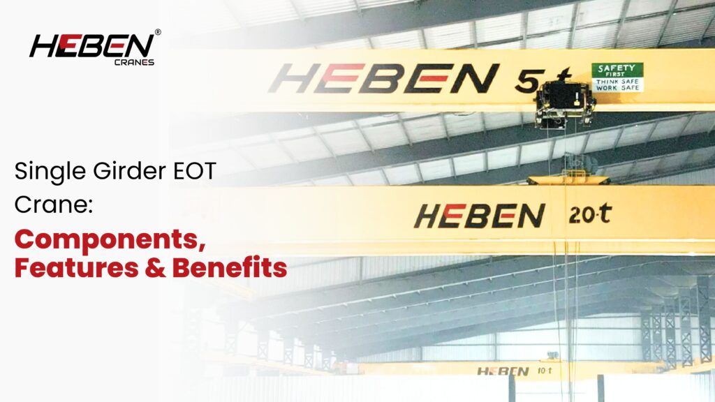
Introduction Most facilities buying their first overhead crane focus on capacity and price, then discover the equipment doesn’t match their building height, bay width, or duty pattern. The single girder EOT crane—Electric Overhead Travelling—solves light to moderate material handling requirements at 30-40% lower cost than double girder alternatives, but only when specified correctly. Here’s the uncomfortable truth: most buyers underestimate how much component quality determines long-term reliability, not just purchase price. This guide covers every major component, the features that separate well-built systems from budget ones, technical specifications, and the applications where single girder design delivers optimal value. Main Structural Components The bridge girder is a single horizontal beam of fabricated steel, typically box-section construction. Grade IS 2062 or equivalent structural steel, stress-relieved after welding, resists deflection under repeated loading. End carriages attach to both ends of the girder and carry the wheel assemblies that travel along runway rails. Drive end trucks include geared motors; non-drive end trucks use passive wheels. Alignment between end trucks determines travel straightness and wheel wear. Runway beams and support columns form the fixed infrastructure. These carry all dynamic and static loads from the crane system and must be structurally verified before installation. Lifting and Hoisting System The electric wire rope hoist is the core lifting unit. It consists of a drum motor, gear reducer, rope drum, wire rope, and hook block assembly mounted on the trolley. The trolley travels along the bottom flange of the bridge girder on precision-machined wheels. Cross-travel speed typically runs 2-20 metres per minute depending on application requirements. Hook blocks include safety latches, swivel bearings, and forged-steel hooks rated to the crane’s working load limit. The sheave arrangement determines load travel ratio and lifting speed. Electrical and Control Components Bridge and trolley drive motors typically use AC squirrel cage or variable frequency drive (VFD) systems. VFD controls allow stepless speed adjustment from near-zero to full speed, cutting load swing and improving positioning accuracy. Control panels house motor starters, overload relays, and protection circuits. Pendant controls hang from the bridge for operator use at floor level. Radio remote controls add mobility for complex multi-point lifts. Power delivery uses either a conductor busbar system or cable festoon along the runway. Busbar suits permanent high-use installations; festoon suits shorter spans and lower duty cycles. Safety and Limit Devices Every properly built single girder EOT crane includes a defined set of protection devices: Overload protection relay: cuts power when load exceeds rated capacity Upper and lower limit switches: prevent hoist over-travel in both directions Bridge and cross-travel limit switches: stop movement at runway and girder ends Emergency stop: accessible from pendant and remote controls Electromagnetic brakes: hold loads during power interruption Slack rope detection: protects wire rope from coiling damage These are not optional extras. Missing any one of them creates liability and operational risk. Key Features Single girder design concentrates key advantages in three areas: Space efficiency: The hoist runs on the bottom flange of the girder, keeping the overall crane height lower than double girder alternatives. Facilities gain 300-500mm of additional hook height from the same building envelope. Lightweight construction: The single beam weighs 30-40% less than a comparable double girder bridge. Lighter runway beams, simpler support columns, and reduced foundation loads follow. Modular assembly: Sections bolt together on site rather than requiring heavy lifting equipment for installation. A 10-ton crane with 15-metre span typically assembles in 2-3 days. Technical Specifications Standard single girder EOT crane parameters: Capacity: 1-20 tons (most applications use 1-10 tons) Span: 7.5-31.5 metres Lifting height: 3-30 metres depending on hoist and building height Lifting speed: 0.5-12 metres per minute Bridge travel speed: 20-80 metres per minute Duty class: A3-A5 (light to moderate use cycles) Work environment: -20°C to +40°C standard Benefits and Advantages Cost advantages extend beyond purchase price. Installation runs 40-50% faster than double girder systems, reducing labour and downtime costs. Maintenance access is simpler. Fewer structural components mean fewer inspection points. Annual maintenance costs run 20-30% lower than double girder systems for equivalent capacity. The 25-35% lower purchase price versus double girder at equivalent tonnage recovers in under two years for facilities with moderate duty cycles. One underappreciated advantage: single girder cranes suit retrofit projects in buildings with limited structural capacity. The lighter weight fits buildings that would require reinforcement for double girder systems. Applications and Use Cases Single girder EOT cranes work across a wide industrial range: Warehousing and logistics: pallet handling, loading dock operations, storage retrieval Manufacturing: component assembly, machine loading, work-in-process movement Automotive: sub-assembly handling, parts feeding to production lines Pharmaceuticals and food processing: clean-room compatible variants with sealed electrical systems Light fabrication and maintenance: workshop bays, equipment service areas The 10-ton capacity threshold covers approximately 80% of light manufacturing material handling requirements, making single girder the dominant crane type in these sectors. FAQs What’s the maximum practical span for single girder EOT cranes? Standard designs handle up to 31.5 metres. Beyond 25 metres, girder deflection becomes a design constraint and engineers specify heavier section beams. Above 31.5 metres, double girder construction becomes structurally and economically preferable. How long does installation take? A standard 5-10 ton single girder crane with 15-metre span installs in 2-4 days including runway installation, crane assembly, electrical connection, and load testing. Larger spans or complex buildings extend this to 5-7 days. Can single girder cranes handle continuous shift operations? Yes, within their duty class. A3 suits 8-hour intermittent use. A5 handles moderate continuous cycles. Beyond A5, double girder design provides the structural durability heavy-duty continuous operations demand. What’s the difference between wire rope and chain hoists? Wire rope hoists suit heavier capacities (1 ton upward) and longer lift heights with higher speed. Chain hoists suit lighter loads (up to 5 tons) in compact applications with lower lift heights. Wire rope systems are standard for most industrial single girder EOT applications. How do VFD drives improve performance? Variable frequency drives allow smooth acceleration and deceleration, cutting load swing on every move. They extend motor and brake life
Single Girder Overhead Crane Parts & Accessories Guide
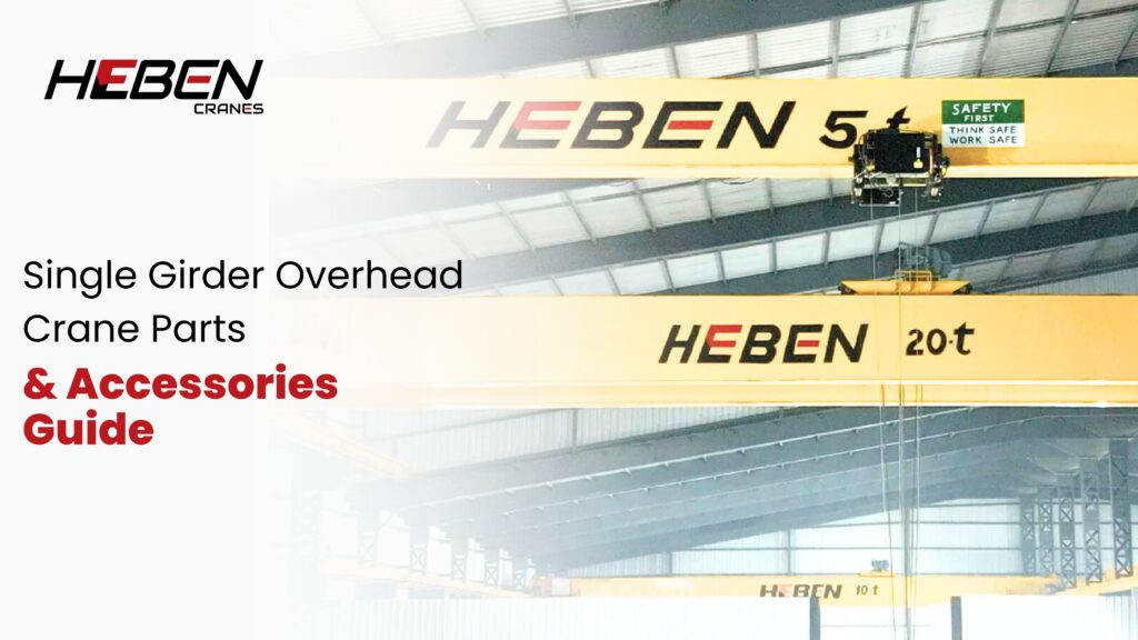
Most buyers finalize a single girder overhead crane based on capacity and span. They rarely ask about hoist duty class, trolley wheel material, or brake type. The crane arrives, gets installed, and works fine for twelve months. Then the hoist brake slips. The trolley wheels develop flat spots. The contactors burn out. Each failure traces back to a part that was under-specified at the order stage. This guide covers every major component category in a single girder overhead crane — structural, mechanical, electrical, and safety — so you know what to specify, what to check, and what to keep in stock. The Main Structure: Girder, End Trucks, and Runway The main girder is the single spanning beam. Most single girder cranes use a standard I-beam for capacities up to 10 tonnes and spans up to 20 meters. Welded box girders handle longer spans and higher capacities with lower deflection. Deflection at rated load must not exceed span divided by 750 per IS standards — exceeding this causes rope drift and positioning errors. End trucks mount at each end of the girder. They carry the bridge wheels, bearings, and long-travel drive assemblies. End truck quality determines how evenly wheel loads distribute onto the runway. Uneven distribution causes one side to wear faster and the bridge to skew during travel. Runway beams support the entire system. Rail type — flat bar, square bar, or crane rail — must match wheel profile and load. Mismatched rail and wheel profiles increase wear by 40% and shorten both components’ service life significantly. Hoist and Lifting Mechanism The hoist is the highest-failure component in any single girder system. It includes a motor, gearbox, drum or chain wheel, rope or chain, and hook block. Wire Rope vs Chain Hoist Wire rope hoists suit lifting heights above 10 meters and capacities above 3 tonnes Chain hoists work for shorter lifts and lighter loads with simpler maintenance Both types must match the crane’s duty class — a mismatch shortens component life regardless of brand Low-headroom hoist-trolley units combine the hoist and trolley into one compact body. They recover 400–600 mm of hook height in restricted bays. For Indian sheds with 6–7 meter height, this difference determines whether you can actually use the full rated lift. Trolley and Cross-Travel System The trolley carries the hoist along the girder’s bottom flange. Wheels run on the lower flange surface. Hardened wheel treads last 3–5 times longer than soft wheels under daily operating conditions. Cross-travel drive options are direct-on-line (fixed speed) or VFD-controlled (variable speed). VFD drives reduce mechanical shock on each start and stop. They extend rope life, reduce load swing, and cut energy use by 30–35%. For facilities running two or more shifts, the energy saving alone justifies the VFD cost within two years. Trolley guide rollers prevent lateral creep on the flange. Without them, the trolley skews, creates uneven wheel contact, and damages the flange edge over time. Long Travel Drive and Wheel Assembly Long travel motors move the bridge along the runway. Crane bridges typically use a single motor driving one end truck, with the other end truck running free. Motor and gearbox sizing must account for bridge weight, hook load, and acceleration force combined. Wheel material matters. Forged steel wheels outlast cast wheels under heavy loads. Flanged wheels prevent derailment on straight tracks. Flangeless wheels suit curved runway sections. End stops and spring or rubber buffers protect the end trucks when the bridge reaches the runway limit. Electrical Panel and Control System The main panel houses contactors, overload relays, inverters, and protection devices. Loose terminal connections are the leading cause of intermittent electrical faults in crane panels. Vibration from daily operation works terminals loose over 12–18 months. Annual panel inspections catch this before it causes a fault under load. Power is delivered via DSL busbar, cable festoon, or cable reel. Busbars suit high-travel-frequency applications. Festoons work for shorter runways and lower cycle rates. Cable reels are compact but require regular drum inspection. Pendant push-button stations are standard. Radio remote controls improve operator safety by moving the operator away from directly beneath the load. For cranes handling hot, sharp, or chemically hazardous loads, remote control is not optional — it is a risk reduction requirement. Safety Components and Protection Devices Every single girder crane requires these safety components as a minimum: Hoist up/down limit switches to prevent two-blocking and rope over-run Travel limit switches at both ends of cross-travel and long travel Hoist brake to hold the load on power loss or emergency stop Overload protection via load limiter or torque switch to prevent structural overstress Emergency stop accessible from the pendant and any remote station Warning horn for audible alert during bridge movement Suppliers who omit travel brakes to reduce cost create drift risk. On any runway with a slight gradient, an unbraked bridge will creep when the operator releases the control. This is a statutory non-compliance under IS 3938. Hooks, Ropes, and Load Attachments The hook block is the last link in the load chain. Forged hooks with safety latches and swivel bearings are standard. Hooks must be proof-tested to 200% of working load before installation. Any visible crack, twist, or throat opening beyond 5% of original dimension requires immediate replacement. Wire rope selection depends on reeving arrangement, drum pitch, and working load. Six-strand round strand rope is common. Rotation-resistant ropes suit single-fall reeving to prevent load spin. Rope end terminations — wedge sockets or swaged ferrules — need inspection at each routine service. Standard load accessories add versatility: Lifting beams for long or awkward loads C-hooks for coil, pipe, and ring handling Magnetic lifters for steel plate and sheet Vacuum lifters for smooth, non-ferrous surfaces Each accessory reduces the effective crane capacity. A 5-tonne crane with a 300 kg lifting beam has a net load capacity of 4.7 tonnes. This must be marked and known to every operator. Performance Accessories Worth Specifying These accessories don’t appear on budget quotations. They appear on maintenance records and
Heavy-Duty Double Girder Crane: Industrial Lifting Guide
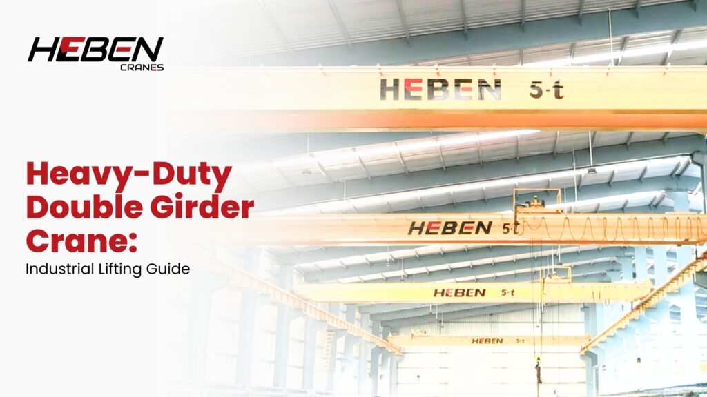
Single girder cranes fail quietly before they fail completely. Facilities running 20-ton loads on A5-rated single girder equipment see major structural fatigue at year 10 instead of year 22—yet most don’t connect the early failure to the original under-specification. Heavy industrial lifting demands a crane built for the actual duty, not the minimum acceptable specification. Double girder cranes exist precisely for this purpose. This guide covers design construction, capacity and span ranges, heavy industry applications, safety systems, drive technology, installation requirements, and maintenance—everything needed to specify a crane that lasts the full service life. What Is a Heavy-Duty Double Girder Crane? A double girder crane uses two parallel main beams forming the bridge structure. The crab unit—hoist and trolley combined—rides on top of both girders. This top-mounted position maximises hook height and supports far greater loads than single girder configurations where the hoist hangs below one beam. Heavy-duty variants are rated A6, A7, or A8 duty class. These classifications handle 20-40+ lift cycles per hour across multi-shift operations running 4,000-8,000+ hours annually. The structural design accounts for fatigue loads, impact factors, and component wear rates matching these intensities. The uncomfortable fact most buyers learn late: a double girder crane costs 30-50% more than a comparable single girder unit. But in A6-A8 service, a single girder alternative doesn’t survive long enough to justify the saving. The premium pays for itself through service life alone. Design Features and Construction The two main girders are box-section beams, welded from steel plate and stiffened internally. This construction resists both vertical deflection and lateral torsion under eccentric loads. End trucks carry wheel assemblies and drive motors at each end of the bridge. Walkway platforms run along both girders. Technicians access the crab mechanism, electrical panels, and drives at crane level without external scaffolding or elevated work platforms. This direct access reduces inspection time and lowers maintenance costs over the crane’s service life. The crab unit contains the hoist motor, gearbox, rope drum, and trolley drive in one compact assembly. Crab designs separate hoist and travel functions mechanically, allowing independent service of each system. Capacity and Span Specifications Load capacity starts at 20 tons and scales to 500+ tons for specialised applications. Standard industrial ranges sit between 20 and 100 tons. Shipbuilding and offshore applications reach 200-500 tons with custom structural engineering. Spans cover 10 to 50+ meters in standard configurations. The dual girder structure maintains acceptable deflection limits across long spans where single girder designs become impractical. At 30 meters span with 50-ton load, single girder deflection would exceed safe limits. Lifting height depends on building clearance and rope drum design. Double girder configurations recover 600-900mm of hook height compared to single girder equivalents because the crab sits above rather than below the bridge. In tight facilities, this difference determines operational capability. Standard Specification Ranges Capacity: 20-500+ tons depending on application class Span: 10-50+ meters Duty class: A6 (heavy), A7 (extra heavy), A8 (severe) Lifting speed: 0.5-8 m/min with VFD control Key Industrial Applications Steel mills run double girder cranes continuously across all three shifts. Ladle cranes handle molten metal. Coil handling cranes move finished product. Charging cranes feed furnaces. Each application demands A7-A8 classification with heat-resistant components and enhanced structural margins. Shipyards use double girder gantry configurations spanning dry docks. Ship section weights reach 100-300 tons. Tandem lift arrangements combine two cranes for single lifts beyond individual rated capacities. Power plants require double girder cranes for turbine installation and maintenance. Lifting heights exceed 20 meters in many turbine halls. Single lifts during outages involve components weighing 50-150 tons with zero tolerance for positioning error. Heavy machinery manufacturing uses A6-class cranes for assembly operations. Press frames, gearboxes, and structural weldments move through fabrication sequences daily. Cycle rates match A6 criteria and justify the structural investment fully. Safety Systems and Controls Overload protection prevents lifts exceeding rated capacity. Load cells in the hoist mechanism trigger automatic cut-off before structural limits are reached. This system operates independently of operator input. Anti-sway technology damps load oscillation during travel. Electronic systems adjust bridge and trolley speeds to counteract pendulum motion. Facilities handling long or awkward loads see measurable cycle time improvements from this feature. Redundant braking provides two independent stopping systems. Primary electromechanical brakes engage on power loss. Secondary mechanical parking brakes hold the load stationary. Both require periodic inspection and adjustment. Core Safety Features Hoist overload cut-off at 100-110% rated load End travel limit switches on hoist, trolley, and bridge Anti-collision systems for multi-crane runways Emergency stop controls accessible from multiple positions Drive and Control Technology Variable frequency drives control all three motions—hoist, trolley, and bridge. VFDs provide soft start reducing mechanical shock, precise speed control for positioning, and energy recovery during controlled lowering. Speed ranges typically include 3-5 preset levels covering rapid transit and precision final positioning. Steel plant applications often add micro-speed capability for ladle positioning at 0.1-0.2 m/min. This granularity prevents collision and product damage during critical lifts. Operator cabins suit applications where load visibility from ground level is inadequate. Cabins mount to the crane bridge and travel with it. Climate control and ergonomic design reduce operator fatigue across 8-12 hour shifts in industrial environments. Installation and Runway Requirements Runway beams carry the full crane load plus dynamic impact factors. Heavy-duty cranes require larger beam sections than single girder installations. Foundation and column design must account for concentrated rail loads, horizontal surge forces, and seismic requirements where applicable. Building structure assessment precedes final crane specification. Existing facilities often need runway upgrades when replacing single girder cranes with double girder units. This structural work adds to total project cost and must be budgeted early. Professional commissioning includes load testing, alignment verification, safety device calibration, and operator training. Skipping formal commissioning creates liability and operational problems that cost more to resolve after the crane enters service. Maintenance and Longevity Preventive schedules for A6-A8 cranes run monthly detailed inspections plus annual comprehensive assessments. Component replacement intervals are shorter than light-duty equipment due to higher cycle counts. Brake