
Industrial Underslung Double Girder Crane Manufacturers
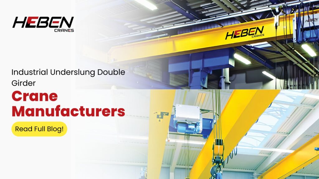
Introduction Your facility has limited headroom and needs a crane that handles loads beyond what single girder underslung systems can manage. Standard EOT cranes require structural headroom you don’t have. Underslung double girder cranes solve this directly — they suspend from the bottom flange of runway beams and use two parallel girders for higher capacity in constrained vertical spaces. This guide covers design fundamentals, technical specifications, applications, installation requirements, and a manufacturer selection framework that goes beyond price comparison to evaluate engineering depth, fabrication quality, and service capability. Understanding Underslung Double Girder Cranes An underslung double girder crane suspends its bridge structure from the bottom flange of runway beams. Two parallel girders span the width of the bay, with the hoist trolley traveling along rails between them. The entire assembly hangs below the runway, preserving vertical clearance while enabling higher capacity than single girder alternatives. The double girder configuration provides greater torsional stability and load distribution. This matters in higher-capacity applications where a single beam would deflect excessively or require impractically large section sizes. Span lengths typically reach up to 15–20 meters with this configuration. The short side approach is the design’s most underrated feature. Double girder underslung cranes bring the hook closer to the building wall than top-running systems, maximizing usable floor area right up to the building edge. Technical Specifications Capacity ranges typically cover 1–25 tons for standard industrial applications, with specialized systems reaching 50 tons. Single girder underslung cranes cap out around 5–10 tons — the double girder design unlocks the capacity band between 10–25 tons in low headroom environments. Key specifications to verify with any manufacturer: Span: Up to 15–20 meters for standard configurations Lifting height: Determined by available headroom minus crane structural depth Duty class: A3–A5 for most industrial applications Hoist type: Wire rope for heavier loads, chain hoist for lighter and more compact requirements Travel speeds: Hoist 3–10 m/min; trolley 10–20 m/min Power supply: Three-phase 415V AC standard Here’s what most buyers don’t check: duty class is routinely under-specified by manufacturers trying to offer lower prices. A crane rated A3 installed in an A5 application fails ahead of schedule. Verify duty classification against your actual lift frequency, not theoretical maximum. Applications and Use Cases Underslung double girder cranes serve facilities where headroom restricts top-running installation but loads exceed what single girder underslung systems can handle. The most common applications: Low headroom workshops: Assembly lines, machine shops, and fabrication bays with 4–6 meter ceiling heights Heavy fabrication: Steel component handling, press shops, and structural fabrication requiring 10–25 ton capacity Multi-crane bays: Multiple underslung units sharing common runway beams for flexible material flow Building width maximization: Short side approach brings the hook to within 300–500mm of the building wall, eliminating dead zones near columns Key Components and Features The main girders use box section or I-beam profiles with custom cantilever extensions at each end. These cantilevers determine the short side approach dimension — a critical spec for maximizing bay coverage. End carriages contain the suspension wheel assemblies that run on the runway beam bottom flange. Wheel design and material affect both load rating and flange wear. Poor end carriage design is the primary cause of premature runway flange degradation. Safety devices are non-negotiable on double girder systems handling loads above 10 tons: Overload limit switches to prevent lifts above rated capacity End travel buffers and limit switches Emergency stop systems Anti-collision devices for multi-crane bays Advantages Over Single Girder Underslung The single-to-double girder upgrade isn’t just about capacity. The structural differences deliver operational advantages: Stability under load: Two girders resist twist forces that cause single girder sway at higher capacities Longer spans: Double girder geometry handles 15–20 meter spans where single girder deflection becomes problematic Higher duty tolerance: Robust construction absorbs dynamic forces from frequent heavy lifts without fatigue Maintenance platform access: Double girder bridges accommodate walkways between girders for in-place servicing Installation and Building Requirements Roof structure verification is the critical first step. The existing building beams must carry combined crane dead weight, rated load, and dynamic factors — typically 1.1–1.3 times static loads. A structural engineer must confirm capacity before crane specification is finalized. Runway beam bottom flange width and thickness determine wheel compatibility. Wider flanges accommodate heavier wheel loads. Many older industrial buildings have adequate roof steel for 10–15 ton underslung cranes without modification. Commissioning sequence for underslung double girder systems: Verify runway beam alignment within 3mm tolerance across full span Install suspension brackets and confirm torque on all fixing points Mount bridge assembly and check girder level Install hoist trolley and connect electrical systems Conduct no-load travel tests in all directions Load test to 125% of rated capacity before production use How to Choose a Manufacturer Step 1: Define Capacity and Duty Document maximum load, typical operating load, and lifts per hour across all shifts. Calculate duty class from actual cycle data, not assumed maximum. Provide this data to prospective manufacturers and ask them to confirm their design addresses it. Step 2: Assess Facility Constraints Measure clear height from floor to lowest roof beam bottom flange. Calculate available hook travel after subtracting crane structural depth. Confirm bay width and column spacing that determines span requirement. Step 3: Evaluate Engineering Capability Ask for general arrangement drawings showing girder sections, cantilever details, and wheel loads. Manufacturers who can’t provide GA drawings early in the process are assembling standard components, not engineering solutions. Custom cantilever dimensions and short side approach calculations separate engineering-led suppliers from catalogue sellers. Step 4: Check Manufacturing Quality Inspect fabrication standards: welding procedures, girder straightness, and surface treatment quality. Confirm load testing infrastructure. Ask whether load testing certificates are issued for every crane or only on request. Step 5: Review Service and Support Evaluate installation capability, spare parts stocking, and AMC structure. For underslung cranes handling 15–25 tons, service response time directly affects production continuity. A manufacturer without regional service presence means extended downtime when breakdowns occur. Common Mistakes to Avoid Most failures trace to three avoidable decisions: Using single
Goliath Cranes vs. Other Cranes: Key Differences Explained
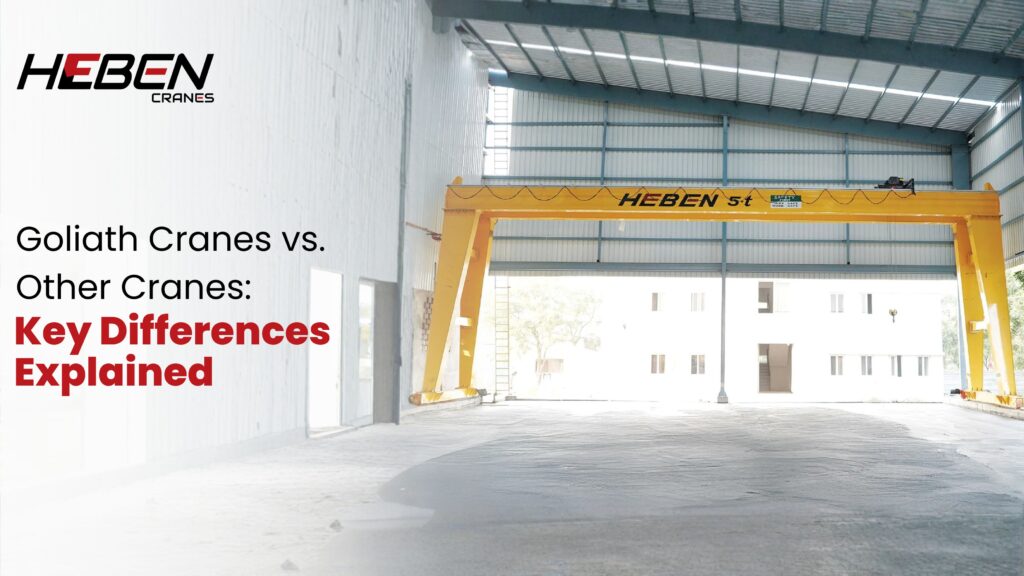
Introduction Most facilities that need heavy lifting default to overhead bridge cranes or mobile cranes without evaluating whether either actually fits the job. The result is either underspecified equipment that fails under load, or overbuilt systems that cost three times more than necessary. Goliath cranes occupy a specific and often misunderstood position in the crane family—not interchangeable with gantry, bridge, mobile, or tower cranes, but purpose-built for applications where those alternatives fall short. This guide explains the structural distinctions, capacity boundaries, cost logic, and application patterns that separate Goliath cranes from every other crane type buyers commonly consider. Defining Goliath Cranes A Goliath crane is a rail-mounted gantry crane with freestanding box-section or truss legs, a heavy-duty double girder bridge, and ground-level travel rails embedded in reinforced foundations. The name reflects scale, not a separate mechanical family. Capacities start at 50 tons and reach 1,000+ tons. Spans run from 30 to 60+ meters. Lifting heights extend to 30 meters on permanent installations. The structural independence is the defining feature. Goliath cranes carry their own support system. No building walls, roof structure, or columns bear any crane load. Goliath vs. Gantry Cranes Gantry cranes are the broader category. They include portable workshop units (0.5-5 tons), industrial gantry systems (5-100 tons), and Goliath cranes at the heavy end. The differences emerge at scale. Standard gantry cranes use lighter A-frame or tubular legs suited to moderate loads. Goliath designs use deep box-section legs engineered for torsional rigidity under extreme dynamic loads. Foundation requirements diverge sharply. Standard gantry cranes mount to surface-level rails. Goliath rail systems require concrete foundations 1-3 meters deep to handle the combined weight of crane and suspended load. Goliath vs. Overhead Bridge Cranes Overhead bridge cranes require building runway beams and columns to bear crane loads. The building becomes part of the crane system. Goliath cranes need none of this. They operate in open yards, outdoor facilities, and sites without roof structure. This independence allows coverage of areas too large or exposed for building-mounted systems. The counterintuitive reality: for spans beyond 30 meters or outdoor applications, Goliath cranes often cost less than the structural reinforcement a building-mounted overhead system would demand. Indoor overhead cranes max out around 40-meter spans in practical terms. Goliath systems serve 60+ meter spans routinely in shipyards and steel yards. Goliath vs. Mobile Cranes Mobile cranes—truck-mounted or crawler—offer site mobility that Goliath systems don’t. They set up, lift, and move on. But cycle time tells a different story. A mobile crane completing 10-15 lifts per day at a fixed site costs 4-6 times more per lift than a permanent Goliath system handling the same volume. Mobile cranes also require ground preparation, outrigger pads, and clear access paths for every lift. Goliath cranes eliminate this setup overhead on permanent sites. Weather constrains mobile crane operations significantly. Wind speeds above 30-40 km/h typically halt mobile crane work. Goliath systems with proper storm anchoring continue operating in conditions that ground mobile equipment. Goliath vs. Tower Cranes Tower cranes excel at vertical reach—serving multi-storey construction where loads move upward through 50-100+ meters. Goliath cranes handle horizontal coverage at lower heights with far greater load capacity. The application overlap is narrow. Tower cranes serve construction projects; Goliath cranes serve permanent industrial facilities. Setup time favors Goliath for long-term operations—tower crane erection and dismantling adds weeks to project schedules. Cost per lift across a five-year horizon favors Goliath cranes heavily for facilities running continuous operations. Key Technical Specifications Goliath crane design addresses challenges that smaller systems don’t face: Leg structure: Deep box-section steel, stress-relieved after welding, resists deflection under asymmetric loads Rail system: Heavy-section rails on reinforced concrete beams, aligned to sub-millimetre tolerance Drive systems: Variable frequency drives on all axes for precise positioning of loads exceeding 100 tons Wind resistance: Storm anchoring systems resist non-operating winds to 150 km/h; operating limits typically 20-28 km/h Electrical infrastructure: High-current busbar systems or cable reels feeding multiple motors simultaneously Applications Where Goliath Cranes Excel Goliath cranes dominate four application categories where alternatives fall short: Shipyards: Hull section assembly, outfitting, and launching where 100-500 ton capacity covers multiple operations simultaneously Steel mills: Slab and coil handling across wide open yards with continuous heavy-duty cycles Container terminals: Inter-yard transfer operations covering multiple lanes and stack rows Heavy fabrication: Large pressure vessel, turbine, and structural steel assembly requiring precision positioning at high capacity Advantages and Limitations Where Goliath systems deliver clear value: Highest available capacity in freestanding crane design Wide coverage without building structure investment Lower cost per lift on high-volume permanent operations 25-35 year service life under proper maintenance Where limitations apply: Site preparation costs are substantial—rail foundations alone run $50,000-$200,000 depending on scale Relocation is impractical once installed Wind sensitivity requires monitoring systems and operating protocols Specialist engineering required for foundation, electrical, and structural design Selection Framework Four questions determine whether a Goliath crane fits: Does the load exceed 50 tons regularly? Below this threshold, standard gantry or overhead bridge cranes handle it more economically. Does the span exceed 25-30 meters? Above this, Goliath structural engineering becomes necessary for stability and deflection control. Is the installation permanent? Goliath cranes justify their foundation investment only on sites operating 10+ years. Is outdoor or open-yard coverage required? Building-mounted alternatives become impractical in these environments. When all four answers point toward yes, Goliath is typically the only practical choice. FAQs Can Goliath cranes be installed indoors? Yes, in large industrial facilities like assembly halls and heavy fabrication shops. The rail system installs on indoor concrete floors. The constraint is ceiling height—Goliath systems need 15-30+ meters of vertical clearance. How long does Goliath crane installation take? Foundation preparation takes 4-8 weeks depending on soil conditions and scale. Rail installation and crane assembly add 4-6 weeks. Total project timelines typically run 3-6 months from order to commissioning. What maintenance do Goliath cranes need? Weekly rail and wheel inspection, monthly lubrication of drive systems and wire ropes, annual comprehensive structural and electrical inspection by qualified engineers. Service intervals depend on
Top Running Crane vs Underhung Crane: Full Technical Guide
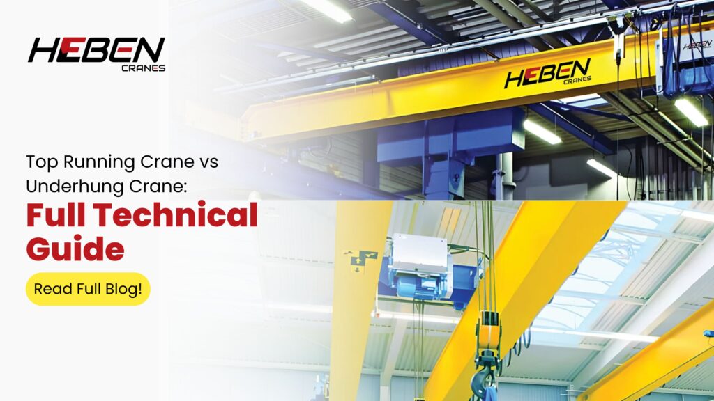
Engineers pick overhead crane configurations the same way most buyers pick cranes — by capacity and cost. They skip the structural analysis, ignore headroom calculations, and overlook the building’s load-bearing limitations. The wrong configuration creates installation problems, reduced hook height, and buildings under stress they were never designed to carry. This guide breaks down the technical and operational differences between top running and underhung cranes. You’ll understand structural requirements, load capacity limits, headroom trade-offs, and the application scenarios where each configuration delivers reliable, long-term performance. What Top Running Cranes Are Top running cranes position their end trucks on top of the runway beams. The bridge girder spans between these rails. The hoist and trolley sit on top of or hang from the bridge girder, depending on single or double girder design. The runway beams carry all crane loads down through columns or wall brackets to the building foundation. This load path is direct and well-understood. It keeps crane loads separate from the roof structure. Top running cranes handle capacities from 5 tonnes to 500+ tonnes. Spans reach 40 meters and beyond. No other configuration matches this range. What Underhung Cranes Are Underhung cranes, also called under-running cranes, position their end trucks on the bottom flange of the runway beams. The bridge girder hangs below. The hoist trolley runs beneath the bridge girder. The runway beams are suspended from the building’s roof or rafter structure. This is the critical difference. Underhung cranes transfer loads upward into the roof, not downward through columns. The roof structure must carry crane dead loads, live loads, and dynamic impact loads simultaneously. Practical capacity limits for underhung systems sit between 5 and 15 tonnes. Engineering theory allows up to 25 tonnes, but local flange bending in the runway and bridge girders makes heavier loads impractical without significant reinforcement. Structural Requirements: What Your Building Actually Needs This is where most installation errors begin. Buyers assume underhung cranes are cheaper because they use the existing building. They frequently are cheaper — until the structural assessment reveals the roof cannot carry the crane loads without reinforcement. Top Running Structural Needs Top running cranes require: Dedicated runway beams, typically wide-flange steel sections Columns or wall brackets sized for vertical wheel loads and lateral thrust Rail clips, end stops, and expansion joints along the runway length Foundation design to handle concentrated column reactions The load path is clean. Crane forces go into dedicated structural members, not the building frame. Underhung Structural Needs Underhung cranes require: Roof or rafter beams with verified capacity for crane dead load, lifted load, and 25–50% dynamic impact Hanger connections from rafter to runway beam, sized for combined vertical and lateral forces Lateral bracing to manage side thrust loads at 20% of rated capacity plus hoist/trolley weight Engineering assessment for every installation — never assumed to fit without calculation Older industrial buildings in India use roof trusses designed for dead load and wind only. Retrofitting an underhung crane into such a structure demands professional structural verification, not a site visit and a quote. Headroom and Hook Height: The Numbers That Matter Top running cranes deliver maximum hook height. The rails sit at the top of the runway beams. The bridge girder rests on the rails. The hoist hangs below the girder. Every component position maximises usable lift height. A 5-tonne top running crane in a 7-meter bay typically achieves 5–5.5 meters of hook height. The same bay with an underhung crane yields 3.5–4 meters because the bridge girder, trolley, and hoist all consume headroom from below. That 1–1.5 meter difference matters when lifting a 2-meter tall machine component over a work table. Top running wins on hook height in any building of equal height. Underhung cranes work in buildings where the roof structure sits lower and dedicated runway beam columns would further reduce available height. The trade-off is hook height, gained in exchange for not introducing new columns into the workspace. Multi-Crane Operations and Flexibility Underhung systems have one clear structural advantage: multiple cranes can share a single runway or pass through each other on intersecting runway systems. An automotive assembly plant running six underhung cranes across crossing runways would require no floor-mounted columns anywhere in the bay. Top running cranes cannot cross each other without complex elevated transfer systems. Each crane needs its own parallel runway set. Adjacent cranes require anti-collision systems and clearance gaps. For facilities running simultaneous multi-crane operations across a large open floor, underhung systems offer better bay utilisation. For facilities needing one or two high-capacity cranes, top running delivers structural efficiency. Maintenance Access and Lifecycle Costs Top running cranes with double girder configurations include maintenance platforms on the bridge girder. Technicians walk on the crane to access hoists, motors, and electrical panels at height. Scheduled maintenance happens without bringing loads to the floor. Underhung cranes provide no platform access. All maintenance requires the crane to return to a ground-level service position. For light-duty applications with infrequent maintenance, this is acceptable. For medium-duty systems with frequent inspection requirements, it adds time and complexity. Rail wear on top running systems concentrates on the top flange of the crane rail. Inspection is visual and straightforward. Underhung runway flange wear occurs on the bottom flange surface and requires closer examination. FAQs Can I convert an underhung crane to top running if my capacity needs increase? Not directly. The two configurations use different structural support systems. A capacity increase typically requires a new runway beam system, column design, and foundation work. Plan for top running from the start if your load requirements may grow beyond 10 tonnes. What is the maximum span for an underhung crane? Engineering guidelines allow spans up to approximately 60 meters, but practical limits sit between 15 and 25 meters due to bridge girder deflection and flange bending at the runway connection. Longer spans require heavier girder sections that increase roof loads significantly. Do underhung cranes need rail? No dedicated crane rail is needed. The end trucks run directly on the bottom
Types of EOT Cranes: Single vs. Double Girder Guide
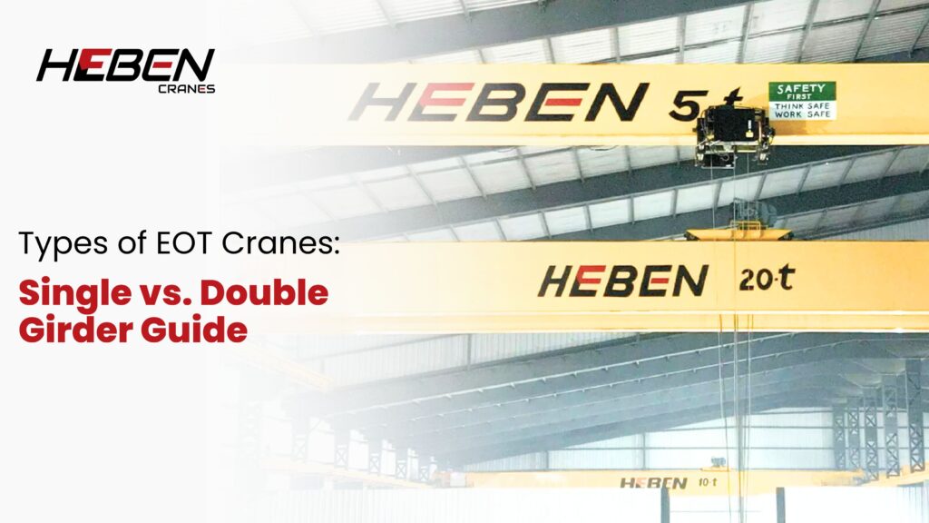
Most facilities spec the wrong EOT crane type and spend years managing the consequences. A single girder crane forced into heavy-duty service wears out in 8-10 years instead of 20. A double girder crane over-specified for light loads adds 30-40% unnecessary cost with no performance return. Electric Overhead Travelling cranes split into two primary configurations—single girder and double girder—and each suits a defined range of load, span, duty, and budget conditions. This guide covers design differences, capacity and span ranges, duty classification matching, installation requirements, and the decision criteria determining which configuration fits your specific project. What Are EOT Cranes? EOT cranes are electrically operated bridge cranes travelling on elevated runway beams. A bridge spans the runway rails. An end truck assembly rides each rail. A hoist and trolley system handles the load. The entire bridge travels along the runway. The trolley travels across the bridge. This two-axis movement covers the full working floor area beneath the crane. Single and double girder variants share this basic structure but differ significantly in how the bridge is built. Single Girder EOT Cranes Single girder cranes use one main beam forming the bridge. The hoist hangs from the lower flange of this beam. The trolley runs below the girder, which limits hook height but reduces overall crane depth. Capacity range sits between 1 and 20 tons. Span covers up to 30-35 meters in standard configurations. Duty classes A3-A5 cover the operational range—light to moderate service with 5-12 lift cycles per hour. Where Single Girder Works Best Workshops and fabrication shops with loads under 15 tons Buildings with limited headroom needing shallow crane profiles Cost-sensitive projects requiring fast installation and lower structural load Operations with moderate duty cycles under 5,000 hours annually Double Girder EOT Cranes Double girder cranes use two parallel main beams. The crab mechanism—hoist and trolley combined—rides on top of the girders. This raises the hook to the maximum available height and supports far heavier loads. Capacity starts at 10-20 tons and scales to 250+ tons. Spans exceed 40 meters routinely. The dual beam structure distributes loads more evenly and resists deflection across long spans. Duty classes A5-A8 apply—moderate to severe service in steel mills, foundries, and multi-shift production facilities. Where Double Girder Works Best Heavy manufacturing with consistent loads above 20 tons Wide-bay facilities requiring spans over 30 meters Operations needing maximum hook height under the roof structure High-cycle environments running intensive multi-shift operations Key Design Differences The hook height difference is the most underestimated factor. Single girder cranes lose 600-900mm of vertical clearance because the hoist hangs below the beam. Double girder cranes recover this height with top-mounted crab units. In a facility with 8-meter clearance, that difference determines whether tall loads can be handled at all. Maintenance access differs fundamentally. Double girder bridges include walkway platforms along the girder tops. Technicians reach the crab, hoist, and electrical systems at crane level. Single girder cranes require external platforms, ladders, or mobile equipment for the same access. Structural weight splits the cost equation. Single girder cranes weigh 30-40% less. Lighter cranes need lighter runway beams and supporting columns. This reduces building structure costs, which often equals or exceeds the crane cost itself in new construction. Duty Class and Application Matching Duty class governs structural design, not just operational tempo. A crane specified below its actual duty class experiences accelerated fatigue. Bearings, welds, and structural joints fail earlier—often before the first major overhaul interval. Single girder suits A3-A5 duty reliably. Double girder handles A5-A8 without structural compromise. The contrarian insight: many facilities running A5 duty with 15-ton loads choose single girder to save cost—then replace the crane at year 12 instead of year 22. The 25% initial saving costs far more over time. Installation and Building Requirements Single girder cranes suit both new and retrofit installations. The lighter structure works with smaller runway beams. Existing building columns often carry single girder loads without reinforcement. Double girder cranes require heavier runway beams and stronger column bases. New construction can account for this in the structural design. Retrofitting an existing building for double girder loads often triggers significant structural work adding 20-35% to project cost. Headroom requirements differ by design. Single girder cranes need less vertical clearance. Double girder systems consume more height due to the crab mechanism sitting above the bridge. Measure available headroom carefully before specifying either type. Frequently Asked Questions Can a single girder crane handle 20-ton loads? Single girder cranes can be manufactured for 20 tons, but the practical upper limit before double girder becomes more cost-effective and structurally reliable is 15-17 tons. At 20 tons on spans beyond 20 meters, deflection and fatigue risk increase measurably. Specify double girder for consistent 20-ton operations above 20-meter spans. What is the lifespan difference between single and double girder cranes? Properly duty-matched single girder cranes last 18-22 years. Double girder cranes in A6-A8 service deliver 20-25 years when maintained correctly. The gap closes when single girder cranes are run above their rated duty class—where service life drops to 10-14 years. Matching duty class to actual operating intensity determines lifespan more than girder count. Does double girder always cost more installed? Equipment cost is higher—typically 30-50% above equivalent single girder. But total installed cost depends on building structure. In new construction where columns are designed for double girder loads from the start, the cost gap narrows. In retrofits, structural upgrades can make double girder total project cost 60-80% higher than single girder. Which type suits a 10-ton, 20-meter span application? Single girder handles this confidently at A3-A5 duty. The span and load sit well within standard single girder capability. Double girder would over-specify the requirement, adding unnecessary cost. Only upgrade to double girder here if the duty class exceeds A5 or if hook height is a critical constraint. How do control systems differ between types? Control systems—pendant, wireless remote, or cabin—apply to both types equally. Double girder cranes more commonly include operator cabins because the larger bridge structure accommodates cabin mounting
Underslung vs. EOT Crane: Key Differences and Advantages
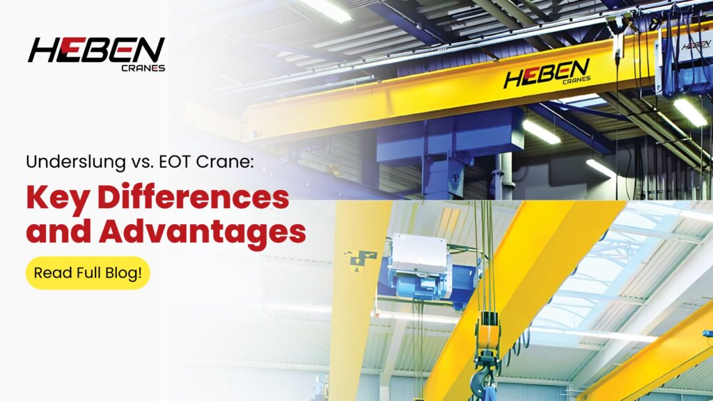
Introduction Your workshop has limited headroom, and a standard EOT crane won’t fit. Or your facility handles 50-ton loads and an underslung system won’t hold. Either way, selecting the wrong crane type means expensive structural changes, operational limits, or both. Underslung cranes hang from the bottom flange of runway beams and suit compact, low-headroom spaces. EOT cranes ride on top of runway beams and handle heavier loads across longer spans. This guide covers structural differences, capacity ranges, installation requirements, operational trade-offs, and a five-step selection process to match crane type to your facility’s real constraints. Understanding EOT Cranes An EOT (Electric Overhead Travelling) crane positions its bridge on top of runway beams mounted to building columns. End carriages run along the top surface of these beams. The entire bridge and hoist assembly sits above the runway support level, maximising hook-to-floor distance. Single girder EOT cranes handle loads up to 20 tons with one main beam. Double girder configurations support 20–500+ tons using two parallel beams, with the hoist trolley mounted on top rails. This design delivers maximum hook height and suits heavy continuous-duty operations. Standard EOT span lengths range from 5 to 45 meters. Duty classes from A3 to A7 define the operating intensity. The top-running configuration is the dominant choice in Indian manufacturing plants for good reason: it scales from light workshop use to heavy process-line applications without structural compromise. Understanding Underslung Cranes An underslung (underhung) crane suspends its bridge from the bottom flange of runway beams. The hoist and trolley hang below the bridge, which hangs below the runway. The entire crane sits lower in the building, consuming vertical space from ceiling down rather than from floor up. This design suits facilities where ceiling height restricts top-running installation. Headroom of 3–4 meters becomes workable. The crane uses existing roof structure in many cases, avoiding costly new runway columns altogether. Practical capacity limits sit at 3–10 tons for most underslung installations, with some systems reaching 20 tons. Beyond this threshold, suspension loads strain existing beam structures and the engineering becomes more complex than a purpose-built EOT runway. Structural and Design Differences The core difference is load path. EOT cranes concentrate loads at column-mounted runway beams. The system transfers vertical and horizontal forces directly to building columns through engineered support. Underslung cranes distribute loads across existing roof beams through suspension points. The roof structure bears the crane, not dedicated columns. Headroom is the practical consequence. A top-running EOT crane adds minimal depth between runway beam top and hook at full height. An underslung system adds beam depth, bridge depth, hoist depth, and suspension clearance—all consuming vertical space before the hook begins its travel. In a 5-meter clear height building, this difference can reach 1.2–1.8 meters of lost hook travel. End carriage and girder mounting differ significantly. EOT end carriages ride on wheels along beam tops. Underslung end carriages use trolley wheels running on the beam’s bottom flange. This bottom-flange contact limits load capacity, as standard I-beams aren’t designed for high lateral forces at the flange. Load Capacity and Span Capabilities EOT cranes dominate from 10 tons upward. Double girder systems serve steel mills, automotive plants, and power facilities where 50–200 ton lifts are routine. The engineering scales because dedicated runways and columns handle the increasing loads systematically. Underslung cranes suit workshops, assembly lines, and light manufacturing under 10 tons. Multiple underslung units can share runway beams, creating flexible material flow across a facility without multiple runway systems. This is a practical advantage that EOT configurations rarely match in tight, multi-zone workshops. Here’s the pattern most facility planners miss: underslung cranes handle 90% of light industrial lifting requirements at lower installation cost, yet fewer than 40% of Indian workshops with sub-10-ton needs actually specify them. The default is always EOT, often with structural modifications that cost more than the crane itself. Installation and Building Requirements EOT installation demands engineered runway beams bolted to columns at precise elevations. Alignment within 3–5mm across full span prevents wheel wear and bridge skew. Column reinforcement adds 15–25% to total project cost in older facilities. Underslung systems mount to existing roof beams or new mono-rail supports without column modification in many cases. Installation proceeds faster and with less disruption to running production. Some facilities add underslung cranes above active floor operations with minimal downtime. Cost factors extend past initial installation. EOT systems cost more upfront but accommodate capacity increases. Underslung installations save installation expense but rarely accommodate future load growth beyond the original design. Maintenance and Operational Factors EOT cranes require regular wheel and drive maintenance at runway level. Access via maintenance walkways or elevated platforms is standard practice. Higher loads mean more wear on wheels, rails, and brake systems. Scheduled servicing intervals are typically monthly for drive components. Underslung cranes offer better lateral maneuverability in confined spaces. The suspended design self-stabilises through minor runway misalignments better than top-running wheels. Maintenance access requires working at height from ladders or mobile platforms, which adds time to routine servicing. Tracking stability favours underslung designs in facilities with marginal or older building structures. The bottom-flange contact tolerates slight beam variations that would cause top-running wheel wear in EOT systems. Properly installed EOT runways, however, match or exceed underslung tracking performance. Applications and Use Cases EOT cranes serve heavy manufacturing, steel fabrication, warehouses, railway workshops, and process plants. These environments need maximum capacity, wide span coverage, and proven performance across multiple daily shifts. The infrastructure investment is justified by operational volume. Underslung cranes fit machine shops, electronics assembly, general fabrication, and facilities where ceiling height restricts alternatives. Several underslung units on shared runways create material flow patterns that a single EOT system can’t replicate economically. Hybrid installations combine both types strategically. A heavy EOT crane handles primary production loads while lighter underslung units serve secondary workstations. This approach distributes load handling without duplicating heavy infrastructure across every bay. How to Choose Between Underslung and EOT Step 1: Assess Load and Frequency Document maximum load, typical operating load, and lifts
What is a Goliath and Gantry Crane? Definition and Usage

Introduction Most buyers use “gantry crane” and “Goliath crane” as if they mean the same thing. They don’t, and the confusion leads to misspecified equipment, undersized capacity, or structural overkill for the actual job. Every Goliath crane is a gantry crane, but not every gantry crane is a Goliath. The distinction lies in scale, duty, and deployment context. This guide defines both types clearly, covers structural design, load ranges, typical applications, and the selection criteria that determine which configuration fits your lifting requirement—whether you’re outfitting a fabrication shop or a shipyard. What is a Gantry Crane? A gantry crane is an overhead lifting system that carries its own support structure. Two freestanding legs support a horizontal bridge beam. The hoist and trolley travel along the beam, and the entire assembly moves on ground-level rails or wheels. The defining feature is structural independence. Gantry cranes don’t attach to building roofs or walls. They operate where building-mounted overhead cranes cannot—outdoors, in open yards, or inside facilities without adequate roof structure. Capacities range widely. Small portable gantries handle 0.5-5 tons in workshops and maintenance areas. Large industrial models lift 50-100 tons across spans of 10-35 meters. What is a Goliath Crane? A Goliath crane is a heavy-duty, large-scale gantry crane designed for the most demanding outdoor applications. The term describes scale and capability, not a fundamentally different mechanism. Goliath cranes run on fixed ground-level rails. Their legs are robust box-section or truss structures, engineered for spans reaching 50+ meters and capacities extending to 1,000 tons or more. The scale creates operational realities that standard gantry cranes don’t face. Wind loading, foundation depth, rail gauge, and electrical infrastructure all require specialist engineering at Goliath scale. Here is the counterintuitive reality: Goliath cranes often cost less per ton of capacity than smaller gantry cranes because of economies of scale in structure and drive systems. Key Design Features Both crane types share core structural logic but differ in execution: Leg configurations: A-frame legs: standard for balanced, symmetrical loads Box-section legs: heavy-duty, used on Goliath designs for rigidity Adjustable-height legs: portable gantry variants for uneven terrain Beam types: Single girder: standard for gantry cranes up to 20 tons Double girder: required for Goliath cranes and heavy-duty gantry above 20 tons Truss girder: lightweight option for lower capacities and longer spans Travel systems: Rail-mounted: fixed path, high capacity, precise positioning Rubber-tired: mobile, suited to yards and sites without fixed rails Portal design: fixed foundations for permanent heavy installations Types and Classifications Full Gantry Cranes Both legs travel on parallel rails or wheels. Complete structural independence from any building. Semi-Gantry Cranes One side runs on a building runway beam. The other travels on a ground rail. Suits facilities with partial overhead support. Portable Gantry Cranes Wheeled or caster-mounted units for 0.5-5 ton applications. Repositionable without infrastructure. Suited to maintenance bays, fabrication shops, and temporary sites. Rail-Mounted Goliath Cranes Permanent ground-rail installations handling 50 tons upward. Standard in shipyards, steel mills, and container terminals. Technical Specifications Capacity ranges differ substantially between types: Portable gantry: 0.5-5 tons Industrial gantry: 5-100 tons Goliath cranes: 50-1,000+ tons Span lengths follow the same pattern. Portable units span 3-8 meters. Industrial gantry systems cover 10-35 meters. Goliath cranes reach 50+ meters in shipyard and port configurations. Lifting heights range from 3 meters on workshop portables to 30+ meters on heavy Goliath installations. Travel speeds typically run 5-30 meters per minute for gantry cranes, with Goliath cranes operating at controlled lower speeds due to mass. Applications and Industry Usage Gantry cranes serve a broad application range: Construction sites: steel erection, precast concrete placement Warehouses: loading dock operations, storage retrieval Manufacturing: equipment maintenance, component assembly Power plants: turbine installation and maintenance Goliath cranes concentrate in high-capacity permanent installations: Shipyards: hull assembly, outfitting, launching operations Steel mills: slab handling, coil movement across large yards Container terminals: inter-yard transfer and stack operations Rail yards: heavy rolling stock maintenance and assembly The 50-ton threshold is a practical dividing line. Below it, standard gantry design handles most requirements. Above it, Goliath engineering becomes structurally and economically rational. Advantages and Limitations Advantages of both types: No building structure required Wide coverage area without fixed overhead infrastructure Scalable from light workshop use to heavy industrial deployment Suitable for indoor and outdoor environments Limitations to plan for: Ground preparation for rails adds cost and time Wind loading in outdoor installations requires anchoring systems Longer spans reduce effective capacity due to structural deflection Goliath cranes require specialist foundation engineering and electrical infrastructure Selection Guide Four factors determine the right choice: Load requirement: Under 20 tons—standard gantry. Above 50 tons—Goliath design. Between 20-50 tons, span and duty cycle decide. Mobility need: Frequent repositioning favors portable or wheeled gantry. Fixed heavy-duty operations favor rail-mounted Goliath. Span coverage: Under 25 meters, standard gantry handles it. Beyond 30 meters, Goliath structural engineering becomes necessary. Environment: Indoor workshops suit portable and semi-gantry designs. Outdoor yards and ports suit rail-mounted Goliath configurations. FAQs Are all Goliath cranes gantry cranes? Yes. Goliath is a classification of gantry crane, not a separate crane family. The term describes high-capacity, large-span, heavy-duty gantry systems used in demanding outdoor and industrial environments. What foundation does a Goliath crane need? Rail-mounted Goliath cranes require reinforced concrete rail beams embedded to depths of 1-3 meters depending on soil conditions and load. Foundation engineering is a significant portion of total project cost. Can gantry cranes operate in wind? Operating limits typically run 20-28 km/h. Non-operating storm anchoring systems resist winds up to 150 km/h. Exposed outdoor installations need wind monitoring systems and automatic rail clamps. What’s the typical service life for these cranes? Standard industrial gantry cranes deliver 15-20 years with proper maintenance. Goliath cranes, built to heavier duty standards with more robust components, commonly reach 25-35 year service lives. Can I convert a standard gantry to a Goliath configuration later? Not practically. The leg structures, rail systems, foundations, and drive systems differ substantially. Capacity upgrades beyond the original design envelope require full replacement. Conclusion Gantry cranes provide
Industrial EOT Cranes: Types, Features, and Applications
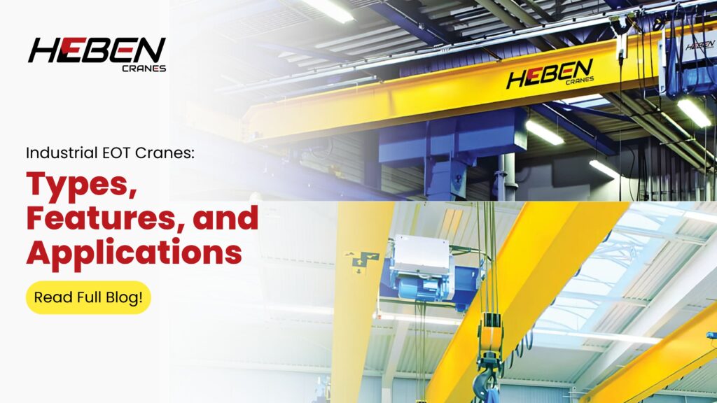
Most factories choose EOT cranes by price and capacity alone. They buy a 15-tonne system because it fits the budget. Six months later, the crane runs constantly, the hoist overheats, and the maintenance team discovers the duty class was rated for occasional use, not continuous production. The crane works — until it doesn’t. This guide explains how to match EOT crane type, features, and duty classification to your actual material handling demands. You’ll learn the structural differences between single and double girder systems, the duty class framework that determines component life, and the application-specific features that separate efficient operations from chronic breakdowns. What EOT Cranes Do in Industrial Operations EOT stands for Electric Overhead Traveling. The crane moves on rails mounted to the building structure. It covers the full bay length and width without occupying floor space. The system consists of a bridge girder, end carriages with wheels, a hoist for vertical lift, and controls for operator input. Unlike mobile cranes or forklifts, EOT cranes handle repetitive lifting in a fixed area with precise positioning and no fuel costs. Capacity ranges from 500 kg to 500 tonnes. Spans reach 40 meters in industrial bays. The crane delivers materials to workstations, moves production between process stages, and loads vehicles at dispatch zones. Single Girder vs Double Girder: The Core Decision Single girder cranes use one main beam. The hoist hangs from the bottom flange and travels along it. This design suits capacities up to 25 tonnes and spans up to 20 meters. The advantages: lower initial cost, simpler installation, reduced building load, and adequate hook height for most workshops. The limitations: restricted lifting height because the hoist sits below the girder, less structural capacity for heavy loads, and limited maintenance access. Double girder cranes use two parallel beams with a crab mechanism on top. This configuration handles 25 tonnes to 500+ tonnes and spans beyond 40 meters. The trade-offs: higher structural cost, increased building load requirements, but maximum hook height, integrated maintenance platforms, and capacity for process-duty cycles in steel plants and heavy industry. You pay more upfront. You gain operational flexibility and longer component life under heavy use. Duty Classes: The Specification Most Buyers Ignore Duty class defines how hard the crane can work. It’s not about capacity. It’s about cycle frequency, load distribution, and operational hours per day. India uses IS/BIS classifications from Class I (light) to Class V (heavy). International standards use FEM/ISO designations from M2 to M9. What the Classes Actually Mean M3/Class II: Occasional use, 1-2 hours per day, light loads M5/Class III: Standard manufacturing, 8 hours per day, moderate cycles M7/Class IV: Heavy production, 16+ hours, frequent full-capacity lifts M8/Class V: Process duty for steel mills, continuous operation A 10-tonne crane rated M3 costs 30-40% less than the same capacity rated M7. The structural steel is thinner. The motor is smaller. The bearings have lower cycle ratings. It works fine for a maintenance shop doing 50 lifts per week. It fails catastrophically in a production line doing 200 lifts per shift.[] Research shows that 65% of premature crane failures result from duty class mismatch, not component defects. Buyers spec capacity correctly. They ignore the usage profile entirely. Safety Features That Separate Compliant from Dangerous Limit switches stop the hoist before it hits the trolley (two-blocking) or unspools rope off the drum. Travel limits prevent collision with end stops or adjacent cranes. These are mandatory, not optional. Brake systems include hoist brakes that hold the load when power cuts, and travel brakes that stop crane motion. Every motion — hoist, cross-travel, long-travel — needs independent braking. Single-brake systems create drift in wind or on inclines. Overload protection shuts down lifting before structural damage occurs. Load cells measure actual weight. Torque limiters sense motor load. Either system must trigger before you exceed the safe working load by more than 10%. Anti-collision sensors detect obstacles or other cranes in the travel path. They reduce speed or stop motion before impact. Plants with multiple cranes operating in the same bay cut collision incidents by 80% when they install active proximity systems. Control Systems and Operational Efficiency Pendant push-button controls hang from the crane. The operator walks with the load. This works for slower operations where load visibility matters more than operator position. Radio remote controls let operators stand at the best vantage point. They improve safety by removing the operator from beneath the load. VFD-based controls provide smooth acceleration, reduced mechanical shock, and 30-40% energy savings over direct-on-line starters. Cabin controls suit high-bay operations where the operator can’t see the load from ground level. Steel mills and scrap yards use cabin cranes for visibility and environmental protection.[] Application-Specific Configurations Steel plants need high-duty cranes with heat-resistant components, cabin controls, and dual hoists for wide loads. Spans reach 40 meters. Capacities exceed 200 tonnes. Duty classes run M7 to M8. Chemical plants require explosion-proof electrical systems, corrosion-resistant coatings, and sealed components. The crane operates in atmospheres where a single spark creates catastrophic risk.[] Engineering workshops use single girder cranes with wire rope hoists, radio remotes, and VFD controls. Capacities range from 5 to 20 tonnes. Duty classes sit at M4 or M5 for standard two-shift operations. Warehouses favor underslung cranes that maximize vertical space, chain hoists for short lifts, and simple controls. The focus is low headroom and cost efficiency, not heavy capacity. How Heben Cranes Engineers EOT Systems Heben matches crane type, duty class, and features to your shift schedule, cycle frequency, and load patterns — not industry averages or catalogue specs. We document the duty class calculation so you know the crane is engineered to your actual usage, not under-spec’d to meet a price target. Our single girder cranes run from 1 to 25 tonnes with VFD controls, sealed bearings, and hardened wheels as standard. Double girder systems handle 25 to 200 tonnes with maintenance platforms, dual brakes, and process-duty ratings for steel, chemical, and heavy manufacturing. We provide installation support, statutory testing, operator training, and long-term
Underslung Double Girder Crane Manufacturer and Supplier
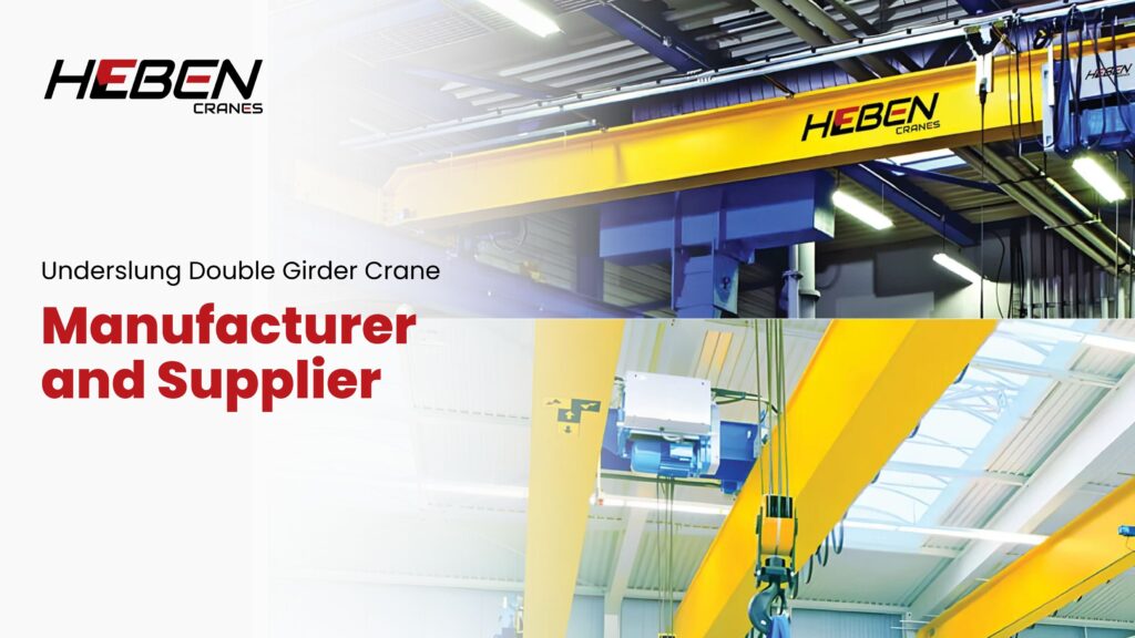
Facilities add overhead cranes and immediately lose 18-30 inches of vertical clearance to runway support structures and crane bridges. This headroom sacrifice forces workflow compromises, limits load heights, or requires expensive building modifications raising roof structures. Underslung double girder cranes reverse this equation by suspending from existing ceiling beams, recovering critical vertical space while eliminating floor support columns. The design solves space constraints that make top-running installations impractical or prohibitively expensive. This guide examines underslung double girder construction, capacity and span capabilities, installation requirements, application advantages, and manufacturer selection criteria ensuring optimal facility integration and long-term performance. Design Principles and Construction Underslung cranes hang from the bottom flange of runway beams rather than riding on top-mounted rails. Two parallel girders form the bridge structure with wheels traveling along beam lower flanges. The trolley and hoist run atop or beneath the bridge depending on configuration. Double girder underslung designs provide superior load distribution compared to single girder variants. Capacities typically range 5-20 tons with spans reaching 60-80 feet. The dual beam structure improves stability and enables heavier loads than single girder underslung cranes limited to 10 tons. Runway beam integration determines installation feasibility. Existing building I-beams must have adequate flange width, structural capacity, and proper alignment. Not all ceiling structures accommodate underslung crane loads without reinforcement or modification. Construction Elements Bridge beams: parallel girders with end trucks and wheel assemblies Trolley system: rides atop bridge with hoist mechanism attached Suspension wheels: travel along runway beam bottom flanges Electrical system: trailing cable or festoon delivering power[] Capacity and Performance Specifications Standard underslung double girder cranes handle 5-20 ton capacities effectively. This range covers light to medium industrial material handling including machine tools, fabricated assemblies, and maintenance operations. Heavier capacities become structurally impractical with underslung configurations. Span limitations exist due to suspended design constraints. Practical spans max out around 60-80 feet before deflection and structural concerns favor top-running installations. Facilities requiring longer spans should evaluate standard overhead crane alternatives. Duty classifications typically fall within A3-A5 light to moderate service. The suspended structure and capacity limitations don’t suit intensive heavy-duty operations demanding A6-A8 ratings. Applications requiring continuous multi-shift cycling or extreme operational intensity need top-running double girder configurations. Advantages Over Top-Running Designs Floor space maximization occurs when underslung cranes use existing ceiling structure eliminating support columns. Production areas, storage zones, and workflow paths remain unobstructed. Facilities where every square foot matters gain significant operational value. Hook height improvement delivers 18-30 inches additional lifting clearance compared to top-running equivalents. The crane suspension below runway beams rather than above them recovers this critical vertical space. Low-headroom applications benefit substantially. Side approach advantages result from suspended design enabling closer wall and edge positioning. Underslung configurations can position loads nearer building perimeters than top-running systems where runway structure creates clearance requirements. This improves coverage across full building width. Installation cost reductions happen when existing ceiling I-beams have adequate capacity. Eliminating new runway columns, foundations, and extensive structural work cuts total installed cost 20-40% compared to freestanding top-running systems in suitable facilities. Installation Requirements and Constraints Runway beam capacity determines feasibility. Existing I-beams must support crane deadweight plus rated load plus dynamic forces from operation. Professional structural analysis verifies adequacy—never assume existing structure suffices without engineering confirmation. Beam alignment affects crane tracking and component wear. Parallel beams must maintain straightness within 3mm tolerance across the span. Misalignment creates uneven loading, accelerated wheel wear, and potential binding during travel. Clearance requirements include adequate spacing for end trucks, electrical systems, and safety margins at both span ends and along travel paths. Obstructions including lights, ducts, and building columns must clear crane envelope during operation. The uncomfortable truth most buyers discover late: roughly 30-40% of facilities lack ceiling structure adequate for underslung crane loads without reinforcement. Initial appeal of “using existing structure” evaporates when structural analysis reveals expensive upgrades matching or exceeding top-running installation costs. Common Applications Retrofits and existing buildings benefit most when adequate ceiling structure already exists. Adding material handling capability without floor-level modifications or production disruption provides substantial value. Historical buildings or facilities with fixed layouts particularly suit underslung solutions. Assembly and production lines use underslung cranes for component positioning, sub-assembly movement, and work-in-progress handling. Close wall approach and unobstructed floor space support efficient workflow layouts. Automotive, electronics, and machinery assembly operations commonly specify underslung designs. Maintenance facilities including repair bays, service shops, and equipment service areas leverage underslung configurations for flexible equipment access. Vehicle maintenance, machinery repair, and heavy equipment service benefit from overhead lifting without floor obstruction. Light manufacturing operations handling moderate loads in the 5-15 ton range find underslung double girder cranes deliver adequate capacity at competitive cost. Machine shops, fabrication facilities, and component production suit the design well. Manufacturer Selection Criteria Engineering expertise in underslung design separates qualified manufacturers from standard overhead crane suppliers. The specialized structural analysis, runway integration, and installation requirements demand specific technical knowledge. Request portfolios demonstrating underslung project experience. Customization capability matters because every installation faces unique ceiling structure, headroom, span, and clearance constraints. Off-the-shelf solutions rarely fit perfectly. Manufacturers offering detailed engineering adaptation to specific facilities deliver better outcomes. Quality documentation including structural calculations, load test certificates, and material traceability validates engineering claims. Legitimate manufacturers provide comprehensive documentation supporting design decisions and regulatory compliance. Service infrastructure availability determines long-term support quality. Underslung crane maintenance requires specialized rigging and access procedures. Verify manufacturers maintain trained technicians and spare parts inventory supporting ongoing operations. Frequently Asked Questions Q: Can any building support underslung double girder cranes? A: No. Existing ceiling I-beams must have adequate structural capacity, proper flange geometry, and correct alignment. Professional structural analysis determines feasibility—roughly 30-40% of facilities need reinforcement or can’t accommodate underslung loads economically. Never proceed without verified engineering approval of existing structure. Q: What capacity limits apply to underslung double girder designs? A: Practical capacity limits fall around 15-20 tons for most underslung double girder configurations. Structural constraints from suspended design, beam flange loading limits, and deflection concerns restrict heavier capacities. Applications requiring 25+ tons should
Gantry and Goliath Cranes: The Ultimate Industrial Guide
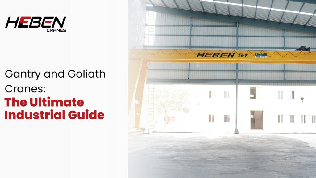
Introduction Your facility needs overhead lifting but lacks the building structure to support bridge cranes. Outdoor yards, storage areas, and bay extensions face this challenge when columns can’t handle runway loads or don’t exist at all. Gantry and Goliath cranes solve this by running on ground-level rails with independent leg support. These systems deliver heavy-duty lifting capability without building-mounted infrastructure. This guide covers operational mechanics, crane types, component specifications, capacity ranges, industrial applications, selection criteria, and maintenance requirements to match the right gantry configuration to your material handling patterns and site constraints. How Gantry and Goliath Cranes Work Gantry cranes use legs that travel on ground rails instead of building-mounted runways. The bridge structure spans between these legs, with a hoist trolley moving along the girder. This creates three-dimensional positioning: vertical lift through the hoist, lateral movement via trolley travel, and longitudinal coverage through gantry travel along the rails. The load path runs from ground foundations through legs to the bridge girder, then down to the hoist and hook. This ground-based support eliminates dependence on building columns and roof structure. The crane stands independently, making it suitable for outdoor yards and facilities without adequate overhead support. Goliath cranes are large-capacity gantry systems, typically double girder designs handling 50-800 tons. The terminology overlaps—what one facility calls a Goliath crane, another terms a heavy-duty gantry. Function and configuration matter more than naming conventions. Types of Gantry and Goliath Cranes Full gantry cranes have legs on both sides traveling on parallel ground rails. This design works best for outdoor yards, storage areas, and facilities where complete independence from building structure makes sense. Semi-gantry cranes run one leg on ground rail while the other side travels on an elevated building-mounted runway. This hybrid reduces cost and floor obstruction when partial building support exists. The configuration suits facilities with adequate structure on one side but not the other. Single girder gantry cranes use one main beam for loads up to 20 tons. Double girder configurations provide the structural capacity for 20-800 ton lifts across longer spans. The choice depends on load requirements and span distance, not preference. Portable gantry cranes are lightweight aluminum or steel frames on wheels or casters. Capacities range from 500kg to 10 tons with adjustable heights. These units relocate easily between work areas for flexible coverage. Key Components The gantry structure consists of vertical legs, horizontal cross beams connecting leg tops, and main girder(s) spanning between. Legs contain drive motors, wheels, and braking systems for travel along rails. Structural design must withstand vertical loads and horizontal forces from acceleration and braking. Hoisting mechanisms include wire rope hoists for heavy-duty applications and chain hoists for lighter loads. The trolley system mounts to the girder and provides cross-travel motion. Drive systems range from manual chain operation to electric motors with variable frequency drives. End trucks house the wheel assemblies, bearings, and drive components. These units transfer crane weight and operational loads to the rails. Wheel design affects tracking performance and maintenance requirements. Control systems vary from pendant push buttons to radio remotes to full operator cabins. Safety devices include travel limit switches, overload protection, emergency stops, and anti-collision systems for multi-crane environments. Technical Specifications Capacity brackets segment into light (1-10 tons), medium (10-50 tons), and heavy (50-800 tons) ranges. Each bracket implies different structural engineering, foundation requirements, and component specifications. Load capacity alone doesn’t define proper selection—duty cycle and lift frequency matter equally. Span lengths range from 5 meters for portable units to 50+ meters for large Goliath installations. Lifting height varies from 3 meters in compact applications to 30+ meters in shipyards and heavy industry. Operating speeds include gantry travel at 20-50 m/min, trolley travel at 15-40 m/min, and hoist speeds from 3-15 m/min. Higher speeds improve productivity but increase structural loads and power requirements. Duty classes from A3 to A8 indicate operating intensity. Outdoor installations need weatherproofing, corrosion-resistant coatings, and wind stability calculations. Power supply typically uses three-phase systems with appropriate electrical protection. Applications Across Industries Manufacturing facilities use gantry cranes in assembly areas, machine shops, and loading docks where building modifications aren’t feasible. The ground-based design adapts to existing layouts without structural intervention. Steel yards, shipbuilding facilities, and ports rely on heavy Goliath cranes for outdoor material handling. Container terminals use massive gantry systems for ship-to-shore operations and yard stacking. These environments need all-weather operation and spans that building structures can’t support. Precast concrete plants, infrastructure projects, and heavy machinery manufacturers choose gantry systems when loads and spans exceed practical limits for forklifts or mobile cranes. Warehouses and logistics operations use them for high-bay storage and loading dock coverage. Advantages and Limitations Independence from building structure is the primary advantage. Gantry cranes work where overhead cranes can’t—outdoor yards, temporary sites, and facilities with inadequate roof support. They relocate more easily than building-mounted systems, though large rail-mounted units still require significant infrastructure. Heavy load capacity and wide coverage area suit applications with substantial material movement. Double girder Goliath cranes handle hundreds of tons across spans that would require prohibitively expensive building structure. Here’s the uncomfortable truth: gantry cranes cost 20-35% more than equivalent overhead cranes when adequate building structure already exists. The legs, wheels, and ground rail system add expense. Choose gantry configurations because site conditions demand them, not for operational preference alone. Foundation and rail requirements create permanent infrastructure. Poor rail alignment causes premature wear and tracking problems. Ground conditions affect foundation design and project cost significantly. Selection Guide Step 1: Document Load Requirements Map maximum weight, typical load range, and lift frequency across shifts. Include safety margins and growth projections. Specify outdoor exposure and environmental conditions that affect design. Step 2: Assess Site Constraints Measure available span, required lifting height, and ground conditions. Check soil bearing capacity for foundation design. Identify space for rail installation and future extensions. Step 3: Choose Configuration Type Select full gantry when both sides need ground support. Pick semi-gantry when one side has building structure. Decide single versus double girder based on capacity
Underslung vs. EOT Crane: Key Differences & Selection Guide
Introduction Most buyers ask for an “EOT crane” when they mean a top-running overhead system. Then they discover their facility lacks the headroom or structural capacity to support it. The confusion stems from terminology—EOT simply means Electric Overhead Travelling, which includes both top-running and underslung configurations. The difference determines whether you need 5 meters of headroom or 3, whether your building needs reinforcement or works as-is, and whether you spend $15,000 or $35,000 for similar capacity. This guide clarifies the structural distinctions, capacity limits, installation requirements, and application patterns that determine which configuration actually fits your facility and operational needs. What an EOT Crane Actually Is EOT stands for Electric Overhead Travelling crane. The term describes any overhead bridge crane that runs on parallel runway beams, powered electrically, and travels horizontally. EOT includes both single girder and double girder designs. Single girder handles 1-20 tons across spans of 7.5-31.5 meters. Double girder extends to 320+ tons with spans reaching 40+ meters. Standard top-running EOT cranes position the bridge girder on top of runway rails. The hoist travels along the top or bottom of the girder depending on design. Typical lifting heights range 3-15 meters for single girder, extending to 30+ meters for double girder configurations. What an Underslung Crane Is An underslung crane is an EOT crane where the bridge girder hangs from the bottom flange of runway beams instead of sitting on top. The entire assembly suspends from ceiling structure. Trolley wheels run on the bottom flange of the girder, with the hoist hanging below. This configuration suits facilities with 3-4 meters of headroom where top-running systems cannot fit. The crane operates within existing vertical space rather than consuming additional height. Capacity typically ranges 0.25-10 tons, occasionally reaching 16 tons in heavy-duty variants. Spans work up to 22.5 meters though most installations stay under 15 meters. Structural and Mounting Differences Top-Running EOT Configuration The bridge girder rests on rails mounted to the top of runway beams. Wheel assemblies roll along these rails, supporting the crane from above. Building structure carries vertical loads through columns or walls. Runway beams must handle crane weight plus maximum lifted load. Underslung Configuration The bridge girder hangs from trolleys or hangers attached to runway beam bottom flanges. The suspension system reverses the load path. Existing building beams often serve as runways without modification. Installation time drops to 2-5 days versus 7-14 days for top-running systems. Key Technical Differences Headroom Requirements Top-running EOT needs the full crane height above the load plus adequate clearance. A 10-ton system typically requires 5-6 meters of total headroom. Underslung design operates within 3-4 meters. The hoist hangs into working space, not above it. Facilities gain 1.5-2.5 meters of effective lifting height from the same building envelope. Capacity and Performance Here’s the uncomfortable reality: underslung systems reach practical limits around 10-16 tons. Beyond this, structural deflection and suspension stresses favor top-running design regardless of headroom. Top-running EOT handles heavier continuous-duty operations. The supported load path provides stability that suspended designs cannot match at higher capacities. Installation and Cost Considerations Underslung installation costs 40-60% below equivalent capacity top-running systems. The savings come from simpler runway preparation and faster assembly. Structural modifications matter more for top-running cranes. Adding robust runway beams, reinforcing columns, or upgrading foundations adds $8,000-$20,000 to projects. Underslung systems often mount to existing building beams without reinforcement. A structural engineer verifies capacity, but modifications rarely exceed $2,000-$5,000. Floor space implications differ minimally. Both configurations preserve ground-level area equally well. Operational Use Cases Underslung Applications Light manufacturing suits underslung perfectly. Assembly lines handling 1-5 ton components across 10-15 meter spans operate efficiently within headroom constraints. Warehousing and logistics facilities use underslung for intermittent lifting—loading docks, storage retrieval, occasional heavy items. Duty cycles stay below 10 lifts per hour. Retrofit situations favor underslung. Existing buildings gain lifting capability without structural upgrades that approach new crane costs. Top-Running EOT Applications Heavy manufacturing demands top-running capacity. Steel fabrication, foundry work, equipment assembly—operations lifting 10+ tons continuously throughout shifts. Long-span facilities need top-running stability. Spans beyond 20 meters develop deflection and vibration issues with underslung design that compromise positioning accuracy. Future capacity expansion justifies top-running investment. A facility expecting load growth from 8 to 15 tons within five years chooses top-running from the start. Safety and Maintenance Safety features overlap substantially. Both configurations include overload protection, limit switches, emergency stops, and similar control systems. Maintenance access differs significantly. Top-running cranes allow walkway installation along the bridge for service during off-shifts. Underslung systems require lifts or scaffolding for major maintenance. Deflection behavior impacts safety margins. Underslung bridges flex more under load, requiring conservative capacity ratings. Top-running designs tolerate higher duty cycles without fatigue concerns. Duty classifications range A1-A5 for both types, but underslung rarely exceeds A3 in practice while top-running commonly operates at A4-A5. Selection Framework Choose Underslung When: Headroom stays under 4 meters Capacity needs remain below 10 tons Operations involve intermittent lifting (under 8 hours daily) Budget prioritizes low initial cost Existing building structure can support suspension loads Choose Top-Running EOT When: Capacity exceeds 10 tons or may grow beyond current needs Continuous heavy-duty cycles (12+ hours daily) Spans exceed 20 meters Maintenance access and long service life matter Building structure supports runway installation FAQs Q: Can I convert underslung to top-running later? A: Not cost-effectively. The conversion requires removing the underslung system, installing new runway beams, and purchasing top-running components—totaling more than initial top-running installation would have cost. Q: What structural verification does underslung need? A: A structural engineer must confirm that ceiling beams, connections, and supporting columns can handle crane weight plus maximum load without exceeding design limits. This typically costs $1,500-$3,000. Q: How does span length affect the choice? A: Underslung works well under 15 meters, acceptably to 20 meters, and poorly beyond. Top-running handles 30+ meter spans without the deflection issues that limit underslung performance. Q: Do both types use the same hoists? A: Yes, electric wire rope hoists work with both configurations. The mounting orientation differs but